Description
Product Description ANSI/ASME B16.47 Weld Neck Flange
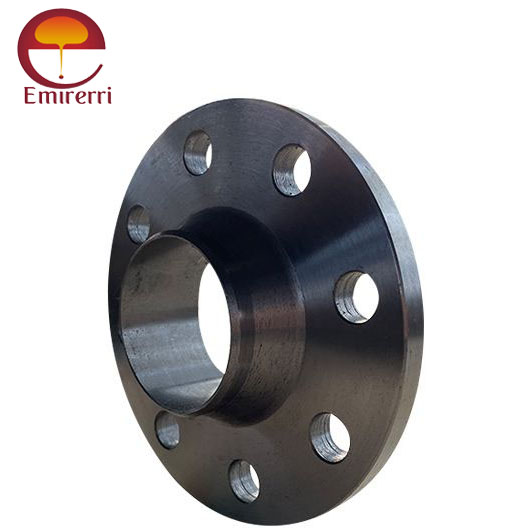
ANSI/ASME B16.47 Weld Neck Flange is a critical component in piping systems, designed to provide a strong, reliable connection between pipes and other equipment. This flange standard is widely used in industries such as petrochemical, oil and gas, and power generation. It ensures that the flange can handle high pressure and temperature applications, offering excellent structural integrity and resistance to stress.
Weld Neck Flanges, as per ANSI/ASME B16.47, feature a long tapered neck that gradually transitions into the pipe, enhancing the strength of the connection and reducing the likelihood of leakage or failure. This design allows for easy welding and creates a robust joint that is resistant to high-pressure conditions.
The ANSI/ASME B16.47 standard covers flanges in two series: Series A and Series B, each with specific dimensional requirements. The flanges are available in a range of sizes and materials, making them versatile for various industrial needs. The high-quality materials used in manufacturing these flanges ensure durability, corrosion resistance, and long service life.
Key Features
- Large Diameter Compatibility:
- Suitable for pipes ranging from NPS 26 to NPS 60.
- Enhanced Strength and Leak Resistance:
- Features a long, tapered hub that provides reinforcement and distributes stress evenly.
- Material Options:
- Available in carbon steel, stainless steel, alloy steel, and other specialized materials.
- Pressure Ratings:
- Meets Class 75 through Class 900 pressure ratings.
- Face Types:
- Offered with raised face (RF), flat face (FF), and ring joint face (RTJ) options for versatile application needs.
ANSI/ASME B16.47 Weld Neck Flange Dimension
ANSI/ASME B16.47 Class 150 Weld Neck Flange Dimensions
| Size in Inch | Size in mm | Outer Diameter | Flange Thickness | Hub OD | Weld Neck OD | Welding Neck Length | Bore | RF Diameter | RF Height | PCD | Weld Face |
| | A | B | C | D | E | F | G | H | I | J |
| 1/2 | 15 | 90 | 9.6 | 30 | 21.3 | 46 | | 34.9 | 2 | 60.3 | 1.6 |
| 3/4 | 20 | 100 | 11.2 | 38 | 26.7 | 51 | | 42.9 | 2 | 69.9 | 1.6 |
| 1 | 25 | 110 | 12.7 | 49 | 33.4 | 54 | | 50.8 | 2 | 79.4 | 1.6 |
| 1 1/4 | 32 | 115 | 14.3 | 59 | 42.2 | 56 | | 63.5 | 2 | 88.9 | 1.6 |
| 1 1/2 | 40 | 125 | 15.9 | 65 | 48.3 | 60 | | 73 | 2 | 98.4 | 1.6 |
| 2 | 50 | 150 | 17.5 | 78 | 60.3 | 62 | | 92.1 | 2 | 120.7 | 1.6 |
| 2 1/2 | 65 | 180 | 20.7 | 90 | 73 | 68 | | 104.8 | 2 | 139.7 | 1.6 |
| 3 | 80 | 190 | 22.3 | 108 | 88.9 | 68 | | 127 | 2 | 152.4 | 1.6 |
| 3 1/2 | 90 | 215 | 22.3 | 122 | 101.6 | 70 | Welding Neck bore is derived from the pipe schedule | 139.7 | 2 | 177.8 | 1.6 |
| 4 | 100 | 230 | 22.3 | 135 | 114.3 | 75 | | 157.2 | 2 | 190.5 | 1.6 |
| 5 | 125 | 255 | 22.3 | 164 | 141.3 | 87 | | 185.7 | 2 | 215.9 | 1.6 |
| 6 | 150 | 280 | 23.9 | 192 | 168.3 | 87 | | 215.9 | 2 | 241.3 | 1.6 |
| 8 | 200 | 345 | 27 | 246 | 219.1 | 100 | | 269.9 | 2 | 298.5 | 1.6 |
| 10 | 250 | 405 | 28.6 | 305 | 273 | 100 | | 323.8 | 2 | 362 | 1.6 |
| 12 | 300 | 485 | 30.2 | 365 | 323.8 | 113 | | 381 | 2 | 431.8 | 1.6 |
| 14 | 350 | 535 | 33.4 | 400 | 355.6 | 125 | | 412.8 | 2 | 476.3 | 1.6 |
| 16 | 400 | 595 | 35 | 457 | 406.4 | 125 | | 469.9 | 2 | 539.8 | 1.6 |
| 18 | 450 | 635 | 38.1 | 505 | 457.2 | 138 | | 533.4 | 2 | 577.9 | 1.6 |
| 20 | 500 | 700 | 41.3 | 559 | 508 | 143 | | 584.2 | 2 | 635 | 1.6 |
| 24 | 600 | 815 | 46.1 | 663 | 610 | 151 | | 692.2 | 2 | 749.3 | 1.6 |
ANSI/ASME B16.47 Class 150 Weld Neck Flange Stud & Bolt Dimensions
| Size in Inch | Size in mm | No of Bolts | Bolt Size UNC | Machine Bolt Length | RF Stud Length | Hole Size | ISO Stud Size | Weight in kg |
| 1/2 | 15 | 4 | 1/2 | 50 | 55 | 5/8 | M14 | 0.6 |
| 3/4 | 20 | 4 | 1/2 | 50 | 65 | 5/8 | M14 | 0.9 |
| 1 | 25 | 4 | 1/2 | 55 | 65 | 5/8 | M14 | 1.4 |
| 1 1/4 | 32 | 4 | 1/2 | 55 | 70 | 5/8 | M14 | 1.4 |
| 1 1/2 | 40 | 4 | 1/2 | 65 | 70 | 5/8 | M14 | 1.8 |
| 2 | 50 | 4 | 5/8 | 70 | 85 | 3/4 | M16 | 2.7 |
| 2 1/2 | 65 | 4 | 5/8 | 75 | 90 | 3/4 | M16 | 3.7 |
| 3 | 80 | 4 | 5/8 | 75 | 90 | 3/4 | M16 | 4.6 |
| 3 1/2 | 90 | 8 | 5/8 | 75 | 90 | 3/4 | M16 | 5.5 |
| 4 | 100 | 8 | 5/8 | 75 | 90 | 3/4 | M16 | 6.8 |
| 5 | 125 | 8 | 3/4 | 85 | 95 | 7/8 | M20 | 8.7 |
| 6 | 150 | 8 | 3/4 | 85 | 100 | 7/8 | M20 | 10.9 |
| 8 | 200 | 8 | 3/4 | 90 | 110 | 7/8 | M20 | 17.7 |
| 10 | 250 | 12 | 7/8 | 100 | 115 | 1 | M24 | 24 |
| 12 | 300 | 12 | 7/8 | 100 | 120 | 1 | M24 | 37 |
| 14 | 350 | 12 | 1 | 115 | 135 | 1 1/8 | M27 | 50 |
| 16 | 400 | 16 | 1 | 115 | 135 | 1 1/8 | M27 | 64 |
| 18 | 450 | 16 | 1 1/8 | 125 | 145 | 1 1/4 | M30 | 68 |
| 20 | 500 | 20 | 1 1/8 | 140 | 160 | 1 1/4 | M30 | 82 |
| 24 | 600 | 20 | 1 1/4 | 150 | 170 | 1 3/8 | M33 | 118 |
ANSI/ASME B16.47 Class 300 Weld Neck Flange Dimensions
| Size in Inch | Size in mm | Outer Diameter | Flange Thickness | Hub OD | Weld Neck OD | Welding Neck Length | Bore | RF Diameter | RF Height | PCD | Weld Face |
| | A | B | C | D | E | F | G | H | I | J |
| 1/2 | 15 | 95 | 12.7 | 38 | 21.3 | 51 | | 34.9 | 2 | 66.7 | 1.6 |
| 3/4 | 20 | 115 | 14.3 | 48 | 26.7 | 56 | | 42.9 | 2 | 82.6 | 1.6 |
| 1 | 25 | 125 | 15.9 | 54 | 33.4 | 60 | | 50.8 | 2 | 88.9 | 1.6 |
| 1 1/4 | 32 | 135 | 17.5 | 64 | 42.2 | 64 | | 63.5 | 2 | 98.4 | 1.6 |
| 1 1/2 | 40 | 155 | 19.1 | 70 | 48.3 | 67 | | 73 | 2 | 114.3 | 1.6 |
| 2 | 50 | 165 | 20.7 | 84 | 60.3 | 68 | | 92.1 | 2 | 127 | 1.6 |
| 2 1/2 | 65 | 190 | 23.9 | 100 | 73 | 75 | | 104.8 | 2 | 149.2 | 1.6 |
| 3 | 80 | 210 | 27 | 117 | 88.9 | 78 | | 127 | 2 | 168.3 | 1.6 |
| 3 1/2 | 90 | 230 | 28.6 | 133 | 101.6 | 79 | Welding Neck bore is derived from the pipe schedule | 139.7 | 2 | 184.2 | 1.6 |
| 4 | 100 | 255 | 30.2 | 146 | 114.3 | 84 | | 157.2 | 2 | 200 | 1.6 |
| 5 | 125 | 280 | 33.4 | 178 | 141.3 | 97 | | 185.7 | 2 | 235 | 1.6 |
| 6 | 150 | 320 | 35 | 206 | 168.3 | 97 | | 215.9 | 2 | 269.9 | 1.6 |
| 8 | 200 | 380 | 39.7 | 260 | 219.1 | 110 | | 269.9 | 2 | 330.2 | 1.6 |
| 10 | 250 | 445 | 46.1 | 321 | 273 | 116 | | 323.8 | 2 | 387.4 | 1.6 |
| 12 | 300 | 520 | 49.3 | 375 | 323.8 | 129 | | 381 | 2 | 450.8 | 1.6 |
| 14 | 350 | 585 | 52.4 | 425 | 355.6 | 141 | | 412.8 | 2 | 514.4 | 1.6 |
| 16 | 400 | 650 | 55.6 | 483 | 406.4 | 144 | | 469.9 | 2 | 571.5 | 1.6 |
| 18 | 450 | 710 | 58.8 | 533 | 457 | 157 | | 533.4 | 2 | 628.6 | 1.6 |
| 20 | 500 | 775 | 62 | 587 | 508 | 160 | | 584.2 | 2 | 685.8 | 1.6 |
| 24 | 600 | 915 | 68.3 | 702 | 610 | 167 | | 692.2 | 2 | 812.8 | 1.6 |
ANSI/ASME B16.47 Class 300 Weld Neck Flange Stud & Bolt Dimensions
| Size in Inch | Size in mm | No of Bolts | Bolt Size UNC | Machine Bolt Length | RF Stud Length | Hole Size | ISO Stud Size | Weight in kg |
| 1/2 | 15 | 4 | 1/2 | 55 | 65 | 5/8 | M14 | 1.4 |
| 3/4 | 20 | 4 | 5/8 | 65 | 75 | 3/4 | M16 | 1.4 |
| 1 | 25 | 4 | 5/8 | 65 | 75 | 3/4 | M16 | 1.8 |
| 1 1/4 | 32 | 4 | 5/8 | 70 | 85 | 3/4 | M16 | 2.3 |
| 1 1/2 | 40 | 4 | 3/4 | 75 | 90 | 7/8 | M20 | 3.2 |
| 2 | 50 | 8 | 5/8 | 75 | 90 | 3/4 | M16 | 4.1 |
| 2 1/2 | 65 | 8 | 3/4 | 85 | 100 | 7/8 | M20 | 5.5 |
| 3 | 80 | 8 | 3/4 | 90 | 110 | 7/8 | M20 | 6.8 |
| 3 1/2 | 90 | 8 | 3/4 | 95 | 110 | 7/8 | M20 | 8.2 |
| 4 | 100 | 8 | 3/4 | 95 | 115 | 7/8 | M20 | 11.4 |
| 5 | 125 | 8 | 3/4 | 110 | 120 | 7/8 | M20 | 14.6 |
| 6 | 150 | 12 | 3/4 | 110 | 120 | 7/8 | M20 | 19.1 |
| 8 | 200 | 12 | 7/8 | 120 | 140 | 1 | M24 | 31 |
| 10 | 250 | 16 | 1 | 140 | 160 | 1 1/8 | M27 | 42 |
| 12 | 300 | 16 | 1 1/8 | 145 | 170 | 1 1/4 | M30 | 64 |
| 14 | 350 | 20 | 1 1/8 | 160 | 180 | 1 1/4 | M30 | 82 |
| 16 | 400 | 20 | 1 1/4 | 165 | 190 | 1 3/8 | M33 | 113 |
| 18 | 450 | 24 | 1 1/4 | 170 | 195 | 1 3/8 | M33 | 145 |
| 20 | 500 | 24 | 1 1/4 | 185 | 205 | 1 3/8 | M33 | 182 |
| 24 | 600 | 24 | 1 1/2 | 205 | 230 | 1 5/8 | M39 | 264 |
ANSI/ASME B16.47 Weld Neck Flange Weight Chart
| Flange Size (inches) | Class 150 (lbs) | Class 300 (lbs) | Class 400 (lbs) | Class 600 (lbs) | Class 900 (lbs) | Class 1500 (lbs) | Class 2500 (lbs) |
| ½ | 2 | 2 | 3 | 3 | 7 | 7 | 8 |
| ¾ | 2 | 3 | 3.5 | 4 | 7 | 7 | 9 |
| 1 | 3 | 4 | 4 | 4 | 8.5 | 8.5 | 13 |
| 1¼ | 3 | 5 | 4.5 | 6 | 10 | 10 | 20 |
| 1½ | 4 | 7 | 8 | 8 | 14 | 14 | 28 |
| 2 | 6 | 9 | 10 | 12 | 24 | 24 | 42 |
| 2½ | 10 | 12 | 14 | 18 | 31 | 31 | 52 |
| 3 | 11.5 | 18 | 18 | 23 | 36 | 36 | 94 |
| 3½ | 12 | 20 | 26 | 26 | 53 | 53 | 146 |
| 4 | 16.5 | 26.5 | 35 | 42 | 86 | 86 | 244 |
| 5 | 21 | 36 | 43 | 68 | 110 | 110 | 378 |
| 6 | 26 | 45 | 57 | 81 | 187 | 187 | 576 |
| 8 | 42 | 69 | 89 | 120 | 268 | 268 | 1068 |
| 10 | 54 | 100 | 125 | 190 | 372 | 372 | 1608 |
| 12 | 88 | 142 | 175 | 226 | 562 | 562 | - |
| 14 | 114 | 206 | 233 | 347 | 685 | 685 | - |
| 16 | 140 | 250 | 295 | 481 | 924 | 924 | - |
| 18 | 165 | 320 | 360 | 555 | 1164 | 1164 | - |
| 20 | 197 | 400 | 445 | 690 | 2107 | 2107 | - |
| 22 | 225 | 465 | 505 | 720 | - | - | - |
| 24 | 268 | 580 | 640 | 977 | - | - | - |
ANSI/ASME B16.47 Weld Neck Flange Tolerance
| Dimension | Tolerance |
| Outside Diameter (OD) | ±1/16 in for ODs up to 24 in |
| ±1/8 in for ODs over 24 in |
| Inside Diameter (ID) | ±1/32 in for diameters up to 10 in |
| +1/16 in for diameters 12-18 in |
| +1/8 in, -1/16 in for diameters over 20 in |
| Diameter of Contact Face | 1/16 in |
| Raised Face | ±1/32 in |
| Tongue and Groove or Male and Female | ±1/64 in |
| Diameter of Hub at Point of Welding | +3/32 in, -1/32 in for hubs up to 5 in |
| +5/32 in, -1/32 in for hubs over 6 in |
| Diameter of Hub at Base | ±1/16 in for hub bases up to 24 in |
| ±1/8 in for hub bases over 24 in |
| Bolt Circle | ±1/16 in |
| Bolt Hole Spacing | +1/32 in |
| Eccentricity of Bolt Circle and Facing | 1/32 in max |
| Length Thru Hub | ±1/16 in for lengths up to 10 in |
| ±1/8 in for lengths over 12 in |
| Thickness | +1/8 in, -0 in for thicknesses up to 18 in |
| +3/16 in, -0 in for thicknesses over 20 in |
Design Features
- Type: Weld Neck Flange
- Hub Length: Long-tapered hub for improved strength and stress resistance.
- Facing Options:
- Raised Face (RF)
- Flat Face (FF)
- Ring Type Joint (RTJ)
- Bore Options: Standard, Extra Strong, Schedule 40/80.
Material
- Carbon Steel: ASTM A105, A350 LF2, A694 F42-F70
- Stainless Steel: ASTM A182 F304/304L, F316/316L, F321, F347
- Alloy Steel: ASTM A182 F11, F22, F5, F9, F91
- Duplex & Super Duplex Stainless Steel: ASTM A182 F51, F53, F55
Applications:
- Oil and gas pipelines.
- Petrochemical refineries.
- Offshore platforms.
- Power plants.
- Chemical processing units.


Reviews
There are no reviews yet.