
Description
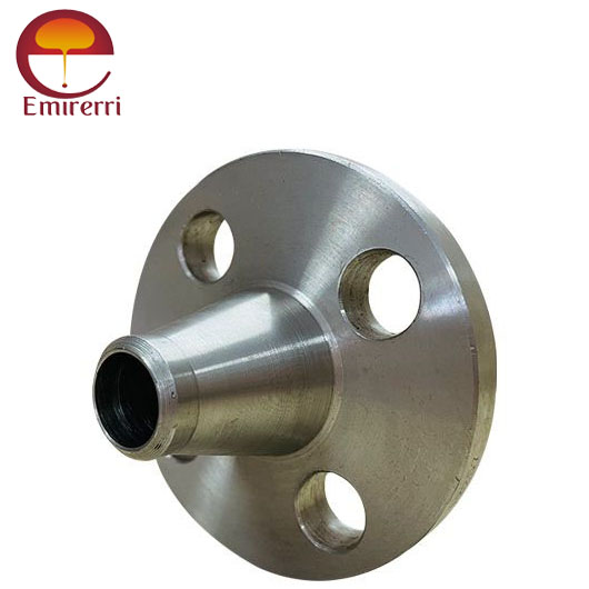
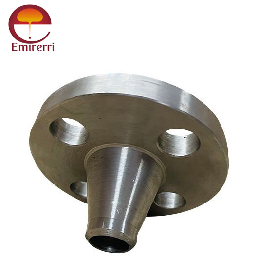
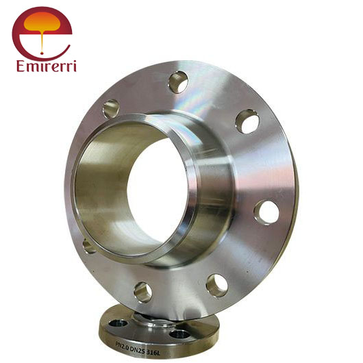
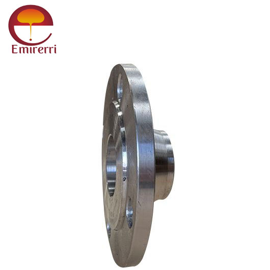
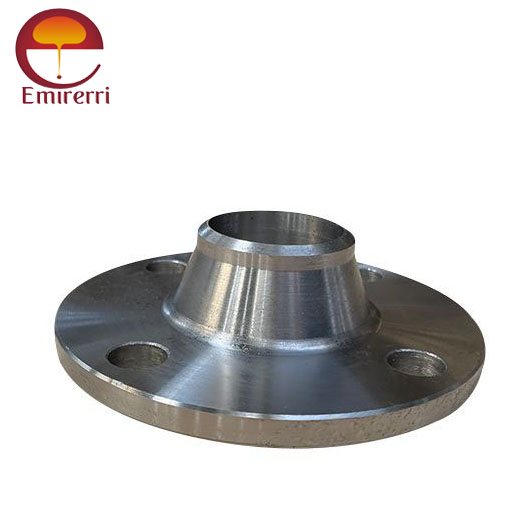
Product Description ANSI/ASME B16.5 Weld Neck Flange
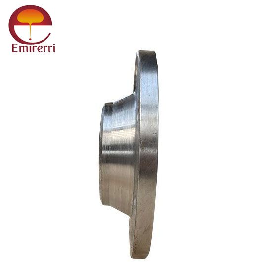
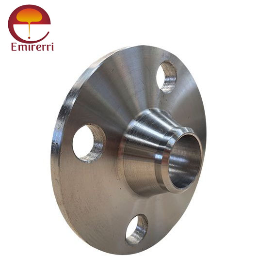
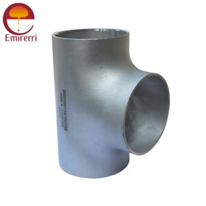
ANSI/ASME B16.5 Weld Neck Flange is a vital component used in industrial piping systems to create secure, high-pressure connections. This flange is designed to provide excellent structural integrity and withstand extreme temperatures and pressures. The Weld Neck Flange features a long, tapered neck that gradually tapers into the pipe, creating a smooth transition that enhances the strength of the connection and minimizes the risk of leaks or stress fractures.
As per ANSI/ASME B16.5, this flange standard covers sizes ranging from 1/2 inch to 24 inches and includes specifications for materials, pressure-temperature ratings, and dimensional tolerances. The design of the Weld Neck Flange allows for a strong welded joint, making it ideal for applications where safety and durability are paramount, such as in the oil and gas, chemical, and power generation industries.
The flange is commonly used in high-pressure, high-temperature environments due to its ability to distribute stresses evenly and resist the forces exerted by the fluid or gas within the pipe. The material selection for ANSI/ASME B16.5 Weld Neck Flanges includes carbon steel, stainless steel, and alloys, ensuring durability, corrosion resistance, and long service life.
Key Features:
- Size Range:
- Available in sizes NPS 1/2″ to NPS 24″ (DN 15 to DN 600).
- Design for Durability:
- The flange features a long tapered neck that connects securely to the pipe, offering additional strength and resistance to mechanical stress.
- Pressure Rating:
- Meets Class 150, 300, 600, 900, 1500, and 2500 pressure ratings.
- Material Options:
- Typically made from carbon steel, stainless steel, and alloy steel, with customization for special alloys based on service conditions.
- Face Types:
- Commonly available with raised face (RF) or flat face (FF) configurations for various sealing requirements.
ANSI/ASME B 16.5 Weld Neck Flange Dimensions
Class 150 Weld Neck Flange Dimensions
Size in Inch Size in mm Outer Diameter Flange Thickness Hub OD Weld Neck OD Welding Neck Length Bore RF Diameter RF Height PCD Weld Face
A B C D E F G H I J
1/2 15 90 9.6 30 21.3 46 34.9 2 60.3 1.6
3/4 20 100 11.2 38 26.7 51 42.9 2 69.9 1.6
1 25 110 12.7 49 33.4 54 50.8 2 79.4 1.6
1 1/4 32 115 14.3 59 42.2 56 63.5 2 88.9 1.6
1 1/2 40 125 15.9 65 48.3 60 73 2 98.4 1.6
2 50 150 17.5 78 60.3 62 92.1 2 120.7 1.6
2 1/2 65 180 20.7 90 73 68 104.8 2 139.7 1.6
3 80 190 22.3 108 88.9 68 127 2 152.4 1.6
3 1/2 90 215 22.3 122 101.6 70 Welding Neck bore is derived from the pipe schedule 139.7 2 177.8 1.6
4 100 230 22.3 135 114.3 75 157.2 2 190.5 1.6
5 125 255 22.3 164 141.3 87 185.7 2 215.9 1.6
6 150 280 23.9 192 168.3 87 215.9 2 241.3 1.6
8 200 345 27 246 219.1 100 269.9 2 298.5 1.6
10 250 405 28.6 305 273 100 323.8 2 362 1.6
12 300 485 30.2 365 323.8 113 381 2 431.8 1.6
14 350 535 33.4 400 355.6 125 412.8 2 476.3 1.6
16 400 595 35 457 406.4 125 469.9 2 539.8 1.6
18 450 635 38.1 505 457.2 138 533.4 2 577.9 1.6
20 500 700 41.3 559 508 143 584.2 2 635 1.6
24 600 815 46.1 663 610 151 692.2 2 749.3 1.6
Class 150 Weld Neck Flange Stud & Bolt Dimensions
Size in Inch Size in mm No of Bolts Bolt Size UNC Machine Bolt Length RF Stud Length Hole Size ISO Stud Size Weight in kg
1/2 15 4 1/2 50 55 5/8 M14 0.6
3/4 20 4 1/2 50 65 5/8 M14 0.9
1 25 4 1/2 55 65 5/8 M14 1.4
1 1/4 32 4 1/2 55 70 5/8 M14 1.4
1 1/2 40 4 1/2 65 70 5/8 M14 1.8
2 50 4 5/8 70 85 3/4 M16 2.7
2 1/2 65 4 5/8 75 90 3/4 M16 3.7
3 80 4 5/8 75 90 3/4 M16 4.6
3 1/2 90 8 5/8 75 90 3/4 M16 5.5
4 100 8 5/8 75 90 3/4 M16 6.8
5 125 8 3/4 85 95 7/8 M20 8.7
6 150 8 3/4 85 100 7/8 M20 10.9
8 200 8 3/4 90 110 7/8 M20 17.7
10 250 12 7/8 100 115 1 M24 24
12 300 12 7/8 100 120 1 M24 37
14 350 12 1 115 135 1 1/8 M27 50
16 400 16 1 115 135 1 1/8 M27 64
18 450 16 1 1/8 125 145 1 1/4 M30 68
20 500 20 1 1/8 140 160 1 1/4 M30 82
24 600 20 1 1/4 150 170 1 3/8 M33 118
Class 300 Weld Neck Flange Dimensions
Size in Inch Size in mm Outer Diameter Flange Thickness Hub OD Weld Neck OD Welding Neck Length Bore RF Diameter RF Height PCD Weld Face
A B C D E F G H I J
1/2 15 95 12.7 38 21.3 51 34.9 2 66.7 1.6
3/4 20 115 14.3 48 26.7 56 42.9 2 82.6 1.6
1 25 125 15.9 54 33.4 60 50.8 2 88.9 1.6
1 1/4 32 135 17.5 64 42.2 64 63.5 2 98.4 1.6
1 1/2 40 155 19.1 70 48.3 67 73 2 114.3 1.6
2 50 165 20.7 84 60.3 68 92.1 2 127 1.6
2 1/2 65 190 23.9 100 73 75 104.8 2 149.2 1.6
3 80 210 27 117 88.9 78 127 2 168.3 1.6
3 1/2 90 230 28.6 133 101.6 79 Welding Neck bore is derived from the pipe schedule 139.7 2 184.2 1.6
4 100 255 30.2 146 114.3 84 157.2 2 200 1.6
5 125 280 33.4 178 141.3 97 185.7 2 235 1.6
6 150 320 35 206 168.3 97 215.9 2 269.9 1.6
8 200 380 39.7 260 219.1 110 269.9 2 330.2 1.6
10 250 445 46.1 321 273 116 323.8 2 387.4 1.6
12 300 520 49.3 375 323.8 129 381 2 450.8 1.6
14 350 585 52.4 425 355.6 141 412.8 2 514.4 1.6
16 400 650 55.6 483 406.4 144 469.9 2 571.5 1.6
18 450 710 58.8 533 457 157 533.4 2 628.6 1.6
20 500 775 62 587 508 160 584.2 2 685.8 1.6
24 600 915 68.3 702 610 167 692.2 2 812.8 1.6
Class 300 Weld Neck Flange Stud & Bolt Dimensions
Size in Inch Size in mm No of Bolts Bolt Size UNC Machine Bolt Length RF Stud Length Hole Size ISO Stud Size Weight in kg
1/2 15 4 1/2 55 65 5/8 M14 1.4
3/4 20 4 5/8 65 75 3/4 M16 1.4
1 25 4 5/8 65 75 3/4 M16 1.8
1 1/4 32 4 5/8 70 85 3/4 M16 2.3
1 1/2 40 4 3/4 75 90 7/8 M20 3.2
2 50 8 5/8 75 90 3/4 M16 4.1
2 1/2 65 8 3/4 85 100 7/8 M20 5.5
3 80 8 3/4 90 110 7/8 M20 6.8
3 1/2 90 8 3/4 95 110 7/8 M20 8.2
4 100 8 3/4 95 115 7/8 M20 11.4
5 125 8 3/4 110 120 7/8 M20 14.6
6 150 12 3/4 110 120 7/8 M20 19.1
8 200 12 7/8 120 140 1 M24 31
10 250 16 1 140 160 1 1/8 M27 42
12 300 16 1 1/8 145 170 1 1/4 M30 64
14 350 20 1 1/8 160 180 1 1/4 M30 82
16 400 20 1 1/4 165 190 1 3/8 M33 113
18 450 24 1 1/4 170 195 1 3/8 M33 145
20 500 24 1 1/4 185 205 1 3/8 M33 182
24 600 24 1 1/2 205 230 1 5/8 M39 264
Weight Chart
Flange Size (inches) Class 150 (lbs) Class 300 (lbs) Class 400 (lbs) Class 600 (lbs) Class 900 (lbs) Class 1500 (lbs) Class 2500 (lbs)
½ 2 2 3 3 7 7 8
¾ 2 3 3.5 4 7 7 9
1 3 4 4 4 8.5 8.5 13
1¼ 3 5 4.5 6 10 10 20
1½ 4 7 8 8 14 14 28
2 6 9 10 12 24 24 42
2½ 10 12 14 18 31 31 52
3 11.5 18 18 23 36 36 94
3½ 12 20 26 26 53 53 146
4 16.5 26.5 35 42 86 86 244
5 21 36 43 68 110 110 378
6 26 45 57 81 187 187 576
8 42 69 89 120 268 268 1068
10 54 100 125 190 372 372 1608
12 88 142 175 226 562 562 -
14 114 206 233 347 685 685 -
16 140 250 295 481 924 924 -
18 165 320 360 555 1164 1164 -
20 197 400 445 690 2107 2107 -
22 225 465 505 720 - - -
24 268 580 640 977 - - -
Tolerance
Dimension Tolerance
Outside Diameter (OD) ±1/16 in for ODs up to 24 in
±1/8 in for ODs over 24 in
Inside Diameter (ID) ±1/32 in for diameters up to 10 in
+1/16 in for diameters 12-18 in
+1/8 in, -1/16 in for diameters over 20 in
Diameter of Contact Face 1/16 in
Raised Face ±1/32 in
Tongue and Groove or Male and Female ±1/64 in
Diameter of Hub at Point of Welding +3/32 in, -1/32 in for hubs up to 5 in
+5/32 in, -1/32 in for hubs over 6 in
Diameter of Hub at Base ±1/16 in for hub bases up to 24 in
±1/8 in for hub bases over 24 in
Bolt Circle ±1/16 in
Bolt Hole Spacing +1/32 in
Eccentricity of Bolt Circle and Facing 1/32 in max
Length Thru Hub ±1/16 in for lengths up to 10 in
±1/8 in for lengths over 12 in
Thickness +1/8 in, -0 in for thicknesses up to 18 in
+3/16 in, -0 in for thicknesses over 20 in
Advantages:
- High mechanical strength and resistance to leakage.
- Ideal for extreme temperature and pressure environments.
- Versatile for a wide range of applications and industries.
Typical Applications:
- Oil and gas infrastructure.
- Chemical and petrochemical industries.
- Power plants.
- Refineries and industrial equipment


Reviews
There are no reviews yet.