

Description
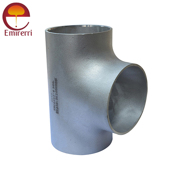
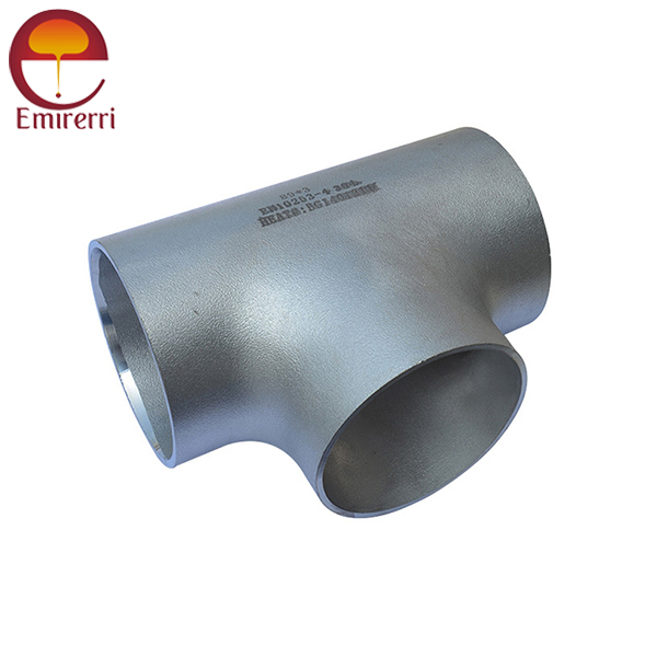
Product Description DIN 2615 Tee
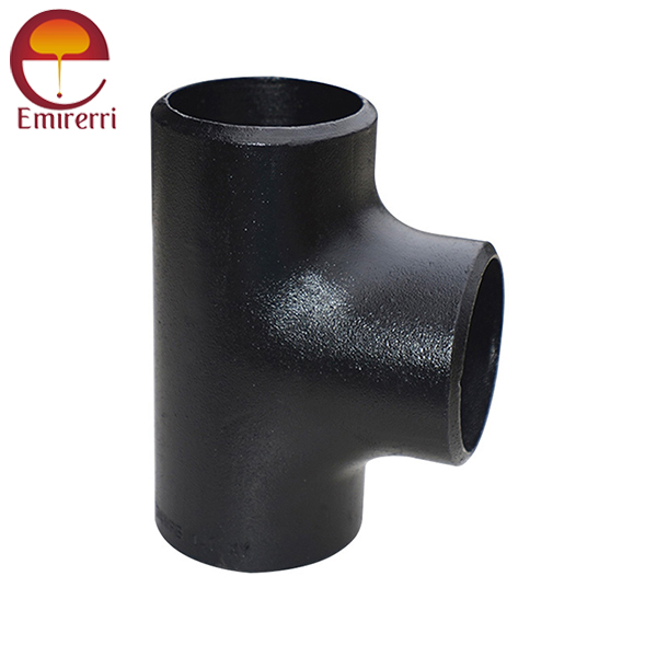
DIN 2615 Tee refers to a type of steel tee fitting used in piping systems to create branches in the pipeline. It is commonly used in industries such as chemical, petrochemical, and power generation. The standard defines various characteristics, including dimensions, material, and manufacturing processes.
There are typically two primary types of tees defined under DIN 2615:
- Tee (equal): Where the branch pipe size is the same as the main pipe size.
- Tee (reducing): Where the branch pipe size is smaller than the main pipe size
DIN 2615 Tee Dimensions (Type A and Type B)
Type A (Straight Branch Tee)
| DN (Nominal Diameter) | d1 (Branch Pipe) | d2 (Main Pipe) | h1 (Branch Length) | h2 (Main Pipe Length) |
|---|---|---|---|---|
| 15 | 15 | 15 | 50 | 60 |
| 20 | 20 | 20 | 50 | 65 |
| 25 | 25 | 25 | 55 | 70 |
| 32 | 32 | 32 | 55 | 80 |
| 40 | 40 | 40 | 60 | 90 |
| 50 | 50 | 50 | 70 | 100 |
| 65 | 65 | 65 | 80 | 120 |
| 80 | 80 | 80 | 90 | 130 |
| 100 | 100 | 100 | 100 | 140 |
| 125 | 125 | 125 | 120 | 160 |
| 150 | 150 | 150 | 130 | 180 |
| 200 | 200 | 200 | 150 | 210 |
| 250 | 250 | 250 | 180 | 250 |
Type B (Reduced Branch Tee)
| DN (Nominal Diameter) | d1 (Branch Pipe) | d2 (Main Pipe) | h1 (Branch Length) | h2 (Main Pipe Length) |
|---|---|---|---|---|
| 15 | 15 | 15 | 45 | 60 |
| 20 | 20 | 20 | 50 | 70 |
| 25 | 25 | 25 | 50 | 75 |
| 32 | 32 | 32 | 55 | 80 |
| 40 | 40 | 40 | 60 | 90 |
| 50 | 50 | 50 | 65 | 100 |
| 65 | 65 | 65 | 75 | 110 |
| 80 | 80 | 80 | 85 | 120 |
| 100 | 100 | 100 | 100 | 140 |
| 125 | 125 | 125 | 110 | 150 |
| 150 | 150 | 150 | 120 | 170 |
| 200 | 200 | 200 | 150 | 200 |
| 250 | 250 | 250 | 180 | 220 |
DIN 2615 Tee Weight Chart
Equal Tee Weight Chart (in lbs)
| Nominal Pipe Size (NPS) | Schedule 40 | Schedule 80 | Schedule 160 |
|---|---|---|---|
| 1/2" | 1.0 | 1.3 | 1.8 |
| 3/4" | 1.4 | 1.8 | 2.5 |
| 1" | 1.8 | 2.4 | 3.2 |
| 1 1/4" | 2.3 | 3.0 | 4.0 |
| 1 1/2" | 3.0 | 4.1 | 5.5 |
| 2" | 4.2 | 6.2 | 8.3 |
| 2 1/2" | 6.7 | 9.8 | 13.0 |
| 3" | 9.4 | 14.1 | 18.7 |
| 4" | 14.5 | 21.6 | 28.8 |
| 5" | 19.0 | 28.3 | 37.7 |
| 6" | 24.0 | 36.0 | 48.0 |
| 8" | 34.0 | 51.0 | 68.0 |
| 10" | 47.5 | 71.0 | 94.0 |
| 12" | 60.0 | 90.0 | 120.0 |
| 14" | 75.0 | 112.0 | 150.0 |
| 16" | 94.0 | 141.0 | 188.0 |
| 18" | 114.0 | 171.0 | 228.0 |
| 20" | 134.0 | 201.0 | 268.0 |
| 24" | 170.0 | 255.0 | 340.0 |
| 30" | 255.0 | 382.5 | 510.0 |
| 36" | 335.0 | 502.5 | 670.0 |
| 42" | 420.0 | 630.0 | 840.0 |
| 48" | 510.0 | 765.0 | 1020.0 |
Reducing Tee Weight Chart (in lbs)
| Run x Branch | Schedule 40 (lbs) | Schedule 80 (lbs) | Schedule 160 (lbs) |
|---|---|---|---|
| 1/2" x 3/8" | 0.3 | 0.4 | 0.6 |
| 3/4" x 1/2" | 0.6 | 0.9 | 1.2 |
| 1" x 3/4" | 0.8 | 1.2 | 1.6 |
| 1 1/4" x 1" | 1.0 | 1.5 | 2.0 |
| 1 1/2" x 1" | 1.2 | 1.8 | 2.5 |
| 2" x 1 1/2" | 1.8 | 2.7 | 3.6 |
| 2 1/2" x 2" | 2.5 | 3.8 | 5.1 |
| 3" x 2" | 3.5 | 5.3 | 7.0 |
| 3" x 2 1/2" | 3.8 | 5.7 | 7.6 |
| 4" x 3" | 5.5 | 8.3 | 11.0 |
| 5" x 4" | 7.3 | 10.9 | 14.4 |
| 6" x 4" | 9.5 | 14.2 | 18.9 |
| 6" x 5" | 10.1 | 15.1 | 20.2 |
| 8" x 6" | 15.5 | 23.3 | 31.1 |
| 10" x 8" | 21.0 | 31.5 | 42.0 |
| 12" x 10" | 28.0 | 42.0 | 56.0 |
| 14" x 12" | 36.0 | 54.0 | 72.0 |
| 16" x 12" | 44.0 | 66.0 | 88.0 |
| 18" x 16" | 56.0 | 84.0 | 112.0 |
| 20" x 16" | 68.0 | 102.0 | 136.0 |
| 24" x 20" | 96.0 | 144.0 | 192.0 |
| 24" x 10" | 80.0 | 120.0 | 160.0 |
DIN 2615 Tee Tolerance
| Parameter | Tolerance |
|---|---|
| Outside Diameter (OD) | ±1% of nominal OD or ±0.5 mm, whichever is greater |
| Wall Thickness (WT) | ±12.5% of specified wall thickness |
| Center-to-End Dimensions | ±1.5% of nominal dimension or ±3 mm, whichever is greater |
| Branch Alignment | ±2 mm for alignment between branch centerline and run centerline |
| Out-of-Roundness | ≤1% of nominal OD |
| End Preparation | ±1 mm for bevel length and ±2° for bevel angle |
| Surface Finish | Free from defects such as cracks, dents, or visible seams |
| Marking Tolerance | Legible and durable markings in accordance with ASME, ANSI, or applicable standards |
Material
- Carbon Steel:
- P235GH (for medium temperature service)
- P265GH (for elevated temperature applications)
- St35.8 (commonly used in pipe fittings)
- Alloy Steels:
- 16Mo3 (for higher temperature service)
- 13CrMo44 (for even higher temperature and pressure ratings)
- X20CrMoV12-1 (for very high-temperature applications)
- Stainless Steel:
- 1.4401 (Austenitic stainless steel, commonly used for corrosion resistance)
- 1.4539 (Alloyed steel with higher corrosion resistance)
- 1.4541 (Stainless steel with good weldability)
- Duplex Stainless Steel:
- 1.4462 (Known for its high strength and resistance to corrosion)
Tolerances
- Outer Diameter:
- The outer diameter of the Tee fitting is usually specified with a ± tolerance, depending on the size. For instance, for smaller diameters, the tolerance might be ±0.5 mm, while for larger diameters, it might be ±1.0 mm or more.
- Wall Thickness:
- The tolerance on the wall thickness is also specified and typically falls within a range such as ±10% of the nominal wall thickness, although this can vary depending on the specific class of the Tee fitting.
- Length of the Fitting:
- The length of the Tee fitting is also subject to tolerance. This is typically given as a maximum allowable variation of a few millimeters (e.g., ±1-2 mm) depending on the size of the fitting.
- Angle of the Branch:
- The angle at which the branch is welded to the main pipe is generally standardized but may have a tolerance range.


Reviews
There are no reviews yet.