Description
Product Description ASME/ANSI B16.9 Reducer
ASME/ANSI B16.9 is a standard that covers factory-made butt-welding fittings, including reducers. These reducers are used in piping systems to connect pipes of different sizes. There are two main types of reducers defined in this standard:
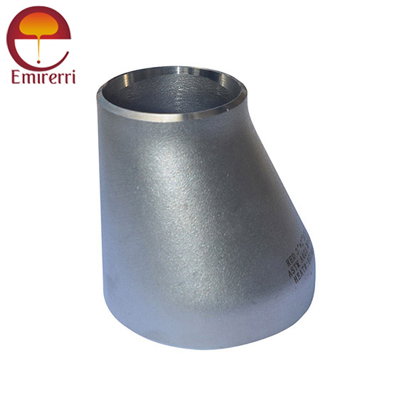
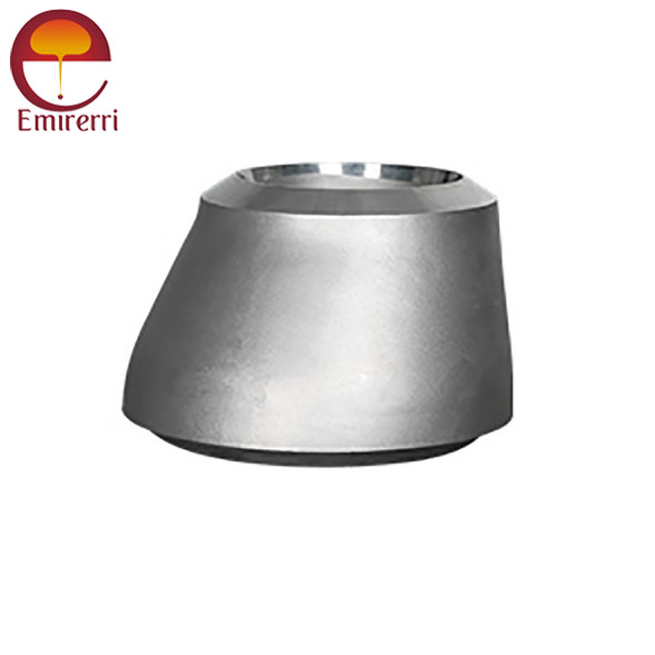
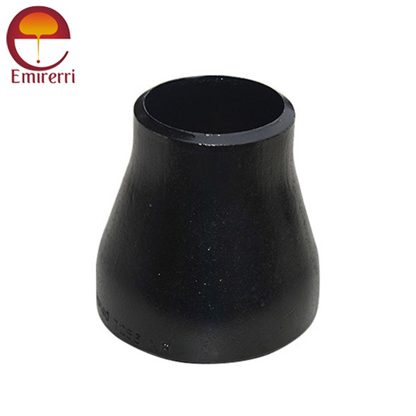
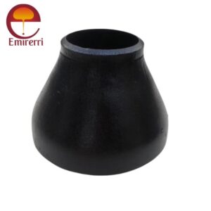
- Concentric Reducer: The centerline of the two pipe ends is aligned. This is typically used when the pipe runs vertically and where the flow is more consistent.
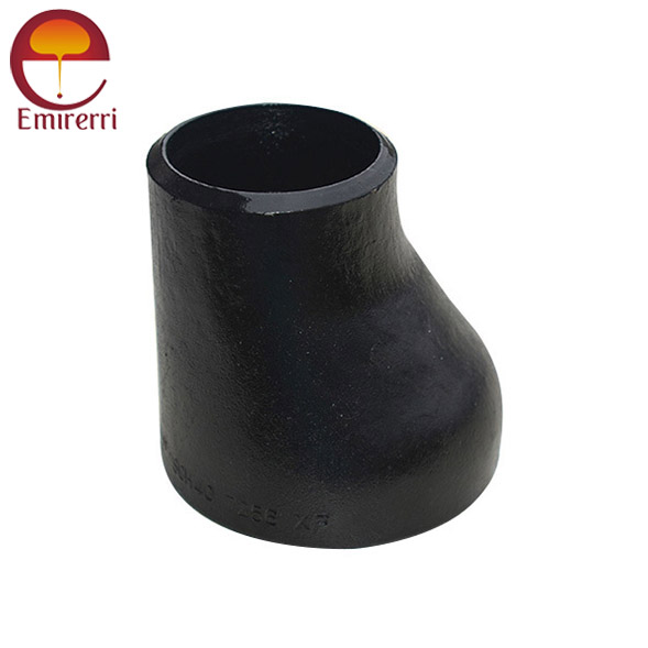
- Eccentric Reducer: The centerline of the two pipe ends is offset, which helps to avoid air pockets and maintains a consistent flow direction, especially in horizontal piping.
ASME/ANSI B16.9 Reducer Concentric and Eccentric Reducer Dimension
| RCD Reiso Code | Ø BIG | | | Ø SMALL | | | Hight H Millimeter | Theoretical Weight Kilogram |
| DN | D mm. | Thickness S mm. | DN | D mm. | Thickness S mm. | | |
| 27 21 | 3/4 | 26.9 | 2.3 | 1/2 | 21.3 | 2.0 | 38 | 0.08 |
| 33 21 | 1 | 33.7 | 2.6 | 1/2 | 21.3 | 2.0 | 50 | 0.09 |
| 33 27 | | | | 3/4 | 26.9 | 2.3 | | 0.09 |
| 42 21 | 1"1/4 | 42.4 | 2.6 | 1/2 | 21.3 | 2.0 | 50 | 0.12 |
| 42 27 | | | | 3/4 | 26.9 | 2.3 | | 0.13 |
| 42 33 | | | | 1 | 33.7 | 2.6 | | 0.14 |
| 48 21 | 1"1/2 | 48.3 | 2.6 | 1/2 | 21.3 | 2.0 | 64 | 0.18 |
| 48 27 | | | | 3/4 | 26.9 | 2.3 | | 0.19 |
| 48 33 | | | | 1 | 33.7 | 2.6 | | 0.20 |
| 48 42 | | | | 1"1/4 | 42.4 | 2.6 | | 0.20 |
| 60 27 | 2 | 60.3 | 2.9 | 3/4 | 26.9 | 2.3 | 76 | 0.30 |
| 60 33 | | | | 1 | 33.7 | 2.6 | | 0.31 |
| 60 42 | | | | 1"1/4 | 42.4 | 2.6 | | 0.32 |
| 60 48 | | | | 1"1/2 | 48.3 | 2.6 | | 0.33 |
| 76 33 | 2"1/2 | 76.1 | 2.9 | 1 | 33.7 | 2.6 | 90 | 0.40 |
| 76 42 | | | | 1"1/4 | 42.4 | 2.6 | | 0.47 |
| 76 48 | | | | 1"1/2 | 48.3 | 2.6 | | 0.48 |
| 76 60 | | | | 2 | 60.3 | 2.6 | | 0.49 |
| 89 42 | 3 | 88.9 | 3.2 | 1"1/4 | 42.4 | 2.6 | 90 | 0.55 |
| 89 48 | | | | 1"1/2 | 48.3 | 2.6 | | 0.61 |
| 89 60 | | | | 2 | 60.3 | 2.9 | | 0.62 |
| 89 76 | | | | 2"1/2 | 76.1 | 2.9 | | 0.63 |
| 114 48 | 4 | 114.3 | 3.6 | 1"1/2 | 48.3 | 2.6 | 100 | 0.85 |
| 114 60 | | | | 2 | 60.3 | 2.9 | | 0.98 |
| 114 76 | | | | 2"1/2 | 76.1 | 2.9 | | 1 |
| 114 89 | | | | 3 | 88.9 | 3.2 | | 1.02 |
| 139 60 | 5 | 139.7 | 4 | 2 | 60.3 | 2.9 | 127 | 1.6 |
| 139 76 | | | | 2"1/2 | 76.1 | 2.9 | | 1.7 |
| 139 89 | | | | 3 | 88.9 | 3.2 | | 1.74 |
| 139 114 | | | | 4 | 114.3 | 3.6 | | 1.76 |
| *168 76 | 6 | 168.3 | 4.5 | 2"1/2 | 76.1 | 2.9 | 140 | 2.6 |
| 168 89 | | | | 3 | 88.9 | 3.2 | | 2.7 |
| 168 114 | | | | 4 | 114.3 | 3.6 | | 2.82 |
| 168 139 | | | | 5 | 139.7 | 4 | | 2.94 |
| 219 114 | 8 | 219.1 | 6.3 | 4 | 114.3 | 3.6 | 152 | 5.03 |
| 219 139 | | | | 5 | 139.7 | 4 | | 5.12 |
| 219 168 | | | | 6 | 168.3 | 4.5 | | 5.18 |
| *273 114 | 10 | 273 | 6.3 | 4 | 114.3 | 3.6 | 178 | 7 |
| *273 139 | | | | 5 | 139.7 | 4 | | 7.2 |
| 273 168 | | | | 6 | 168.3 | 4.5 | | 7.4 |
| 273 219 | | | | 8 | 219.1 | 6.3 | | 7.55 |
| 323 168 | 12 | 323.9 | 7.1 | 6 | 168.3 | 4.5 | 203 | 11 |
| 323 219 | | | | 8 | 219.1 | 6.3 | | 11.1 |
| 323 273 | | | | 10 | 273 | 6.3 | | 11.2 |
Concentric and Eccentric Reducer Weight Chart (in lbs)
| Run x Branch | Schedule 40 (lbs) | Schedule 80 (lbs) | Schedule 160 (lbs) |
| 3/4" x 1/2" | 0.6 | 0.8 | 1.0 |
| 1" x 3/4" | 1.0 | 1.4 | 1.8 |
| 1 1/4" x 1" | 1.4 | 2.0 | 2.6 |
| 1 1/2" x 1" | 1.6 | 2.4 | 3.2 |
| 2" x 1 1/2" | 2.3 | 3.2 | 4.3 |
| 2 1/2" x 2" | 3.0 | 4.4 | 5.9 |
| 3" x 2" | 4.2 | 6.1 | 8.2 |
| 3" x 2 1/2" | 4.4 | 6.5 | 8.7 |
| 4" x 3" | 6.1 | 9.1 | 12.2 |
| 5" x 4" | 8.3 | 12.5 | 16.7 |
| 6" x 4" | 10.3 | 15.5 | 20.7 |
| 6" x 5" | 11.0 | 16.5 | 22.0 |
| 8" x 6" | 16.3 | 24.5 | 32.7 |
| 10" x 8" | 22.0 | 33.0 | 44.0 |
| 12" x 10" | 28.6 | 43.0 | 57.3 |
| 14" x 12" | 37.6 | 56.4 | 75.2 |
| 16" x 12" | 46.6 | 69.9 | 93.2 |
| 18" x 16" | 59.0 | 88.5 | 118.0 |
| 20" x 16" | 71.0 | 106.5 | 142.0 |
| 24" x 20" | 98.0 | 147.0 | 196.0 |
| 24" x 10" | 78.0 | 117.0 | 156.0 |
Tolerance
| Parameter | Tolerance |
| Outside Diameter (OD) | Large End: ±1% of nominal OD or ±0.5 mm (whichever is greater) |
| Small End: ±1% of nominal OD or ±0.5 mm (whichever is greater) |
| Wall Thickness (WT) | ±12.5% of specified wall thickness |
| Reducer Length (L) | ±1.5% of the nominal length or ±3 mm (whichever is greater) |
| Concentricity | Offset ≤5% of the nominal OD at the small end (for concentric reducers) |
| Eccentricity | Offset ≤5% of the nominal OD at the small end (for eccentric reducers) |
| End Preparation | ±1 mm for bevel length and ±2° for bevel angle |
| Out-of-Roundness | ≤1% of nominal OD at both ends |
| Surface Finish | Free from defects such as cracks, dents, or visible seams |
| Marking Tolerance | Legible and durable markings in accordance with ASME, ANSI, or applicable standards |
Design
The design specifies the dimensions, tolerances, material requirements, and manufacturing methods for reducers, ensuring they are suitable for various industrial applications such as oil and gas, chemical processing, and power generation.
Types of Reducers:
- Concentric Reducer: A type in which the centerline of the smaller pipe coincides with the midline of the bigger pipe, resulting in a symmetric, conical shape.
- Eccentric Reducer: A type where the centerline of the smaller pipe is offset from the larger pipe, providing a flat or angled transition.
Applications of ASME/ANSI B16.9 Reducers:
- Piping Systems: Used in industrial piping systems to connect pipes of different sizes, ensuring efficient flow transitions.
- Oil & Gas: Common in oil and gas pipelines to manage varying pipe sizes and ensure smooth fluid flow.
- Chemical & Petrochemical Plants: For handling different pipe sizes, especially in high-pressure and high-temperature environments.
- Power Generation: Applied in power plants where different pipe diameters are needed for steam, water, and gas systems.
- Water Treatment: Utilized in water treatment plants to connect pipes of various sizes in filtration and distribution systems.
Benefits:
- Cost-Effective: Reduces the need for multiple fittings by providing a single solution for pipe size transitions.
- Improved Flow Efficiency: Ensures smooth transitions between pipe sizes, reducing turbulence and improving fluid flow.
- Versatility: Available in a variety of materials, including carbon steel, stainless steel, and alloy steel, for compatibility with diverse industrial requirements.
- Enhanced Durability: Manufactured to meet stringent ASME standards, ensuring longevity and reliability under various pressure and temperature conditions.
- Standardization: Facilitates easy procurement and installation due to standardized dimensions, ensuring compatibility with various piping systems.


Reviews
There are no reviews yet.