


Description
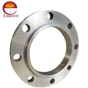
Product Description ANSI/ASME B16.5 Slip on Flange
ANSI/ASME B16.5 Slip on Flange Class 150 is a versatile and cost-effective flange type commonly used in piping systems across various industries. It is made to glide over the pipe and is securely connected by welding on the inside as well as the outside. Its ease of installation and alignment make it an excellent choice for low-pressure and low-temperature applications.
ANSI/ASME B16.5 Slip-On Flange Class 150
Class 150 ANSI/ASME B16.5 Slip on Flange Dimensions
Size in Inch Size in mm Outer Dia. Flange Thick. Hub OD Flange Length RF Dia. RF Height PCD Socket Bore No of Bolts Bolt Size UNC Machine Bolt Length RF Stud Length Hole Size ISO Stud Size Weight in kg
A B C D E F G H
1/2 15 90 9.6 30 14 34.9 2 60.3 22.2 4 1/2 50 55 5/8 M14 0.8
3/4 20 100 11.2 38 14 42.9 2 69.9 27.7 4 1/2 50 65 5/8 M14 0.9
1 25 110 12.7 49 16 50.8 2 79.4 34.5 4 1/2 55 65 5/8 M14 0.9
1 1/4 32 115 14.3 59 19 63.5 2 88.9 43.2 4 1/2 55 70 5/8 M14 1.4
1 1/2 40 125 15.9 65 21 73 2 98.4 49.5 4 1/2 65 70 5/8 M14 1.4
2 50 150 17.5 78 24 92.1 2 120.7 61.9 4 5/8 70 85 3/4 M16 2.3
2 1/2 65 180 20.7 90 27 104.8 2 139.7 74.6 4 5/8 75 90 3/4 M16 3.2
3 80 190 22.3 108 29 127 2 152.4 90.7 4 5/8 75 90 3/4 M16 3.7
3 1/2 90 215 22.3 122 30 139.7 2 177.8 103.4 8 5/8 75 90 3/4 M16 5
4 100 230 22.3 135 32 157.2 2 190.5 116.1 8 5/8 75 90 3/4 M16 5.9
5 125 255 22.3 164 35 185.7 2 215.9 143.8 8 3/4 85 95 7/8 M20 6.8
6 150 280 23.9 192 38 215.9 2 241.3 170.7 8 3/4 85 100 7/8 M20 8.6
8 200 345 27 246 43 269.9 2 298.5 221.5 8 3/4 90 110 7/8 M20 13.7
10 250 405 28.6 305 48 323.8 2 362 276.2 12 7/8 100 115 1 M24 19.5
12 300 485 30.2 365 54 381 2 431.8 327 12 7/8 100 120 1 M24 29
14 350 535 33.4 400 56 412.8 2 476.3 359.2 12 1 115 135 1 1/8 M27 41
16 400 595 35 457 62 469.9 2 539.8 410.5 16 1 115 135 1 1/8 M27 54
18 450 635 38.1 505 67 533.4 2 577.9 461.8 16 1 1/8 125 145 1 1/4 M30 59
20 500 700 41.3 559 71 584.2 2 635 513.1 20 1 1/8 140 160 1 1/4 M30 75
24 600 815 46.1 663 81 692.2 2 749.3 616 20 1 1/4 150 170 1 3/8 M33 100
Class 300 ANSI/ASME B16.5 Slip on Flange Dimensions
Size in Inch Size in mm Outer Dia. Flange Thick. Hub OD Flange Length RF Dia. RF Height PCD Socket Bore No of Bolts Bolt Size UNC Machine Bolt Length RF Stud Length Hole Size ISO Stud Size Weight in kg
A B C D E F G H
1/2 15 95 12.7 38 21 34.9 2 66.7 22.2 4 1/2 55 65 5/8 M14 1.2
3/4 20 115 14.3 48 24 42.9 2 82.6 27.7 4 5/8 65 75 3/4 M16 1.4
1 25 125 15.9 54 25 50.8 2 88.9 34.5 4 5/8 65 75 3/4 M16 1.4
1 1/4 32 135 17.5 64 25 63.5 2 98.4 43.2 4 5/8 70 85 3/4 M16 1.8
1 1/2 40 155 19.1 70 29 73 2 114.3 49.5 4 3/4 75 90 7/8 M20 2.7
2 50 165 20.7 84 32 92.1 2 127 61.9 8 5/8 75 90 3/4 M16 3.2
2 1/2 65 190 23.9 100 37 104.8 2 149.2 74.6 8 3/4 85 100 7/8 M20 4.6
3 80 210 27 117 41 127 2 168.3 90.7 8 3/4 90 110 7/8 M20 5.9
3 1/2 90 230 28.6 133 43 139.7 2 184.2 103.4 8 3/4 95 110 7/8 M20 7.7
4 100 255 30.2 146 46 157.2 2 200 116.8 8 3/4 95 115 7/8 M20 10
5 125 280 33.4 178 49 185.7 2 235 144.4 8 3/4 110 120 7/8 M20 12.7
6 150 320 35 206 51 215.9 2 269.9 171.4 12 3/4 110 120 7/8 M20 17.7
8 200 380 39.7 260 60 269.9 2 330.2 222.2 12 7/8 120 140 1 M24 26
10 250 445 46.1 321 65 323.8 2 387.4 277.4 16 1 140 160 1 1/8 M27 36
12 300 520 49.3 375 71 381 2 450.8 328.2 16 1 1/8 145 170 1 1/4 M30 52
14 350 585 52.4 425 75 412.8 2 514.4 360.2 20 1 1/8 160 180 1 1/4 M30 75
16 400 650 55.6 483 81 469.9 2 571.5 411.2 20 1 1/4 165 190 1 3/8 M33 86
18 450 710 58.8 533 87 533.4 2 628.6 462.3 24 1 1/4 170 195 1 3/8 M33 113
20 500 775 62 587 94 584.2 2 685.8 514.4 24 1 1/4 185 205 1 3/8 M33 143
24 600 915 68.3 702 105 692.2 2 812.8 616 24 1 1/2 205 230 1 5/8 M39 216
ANSI/ASME B16.5 Slip on Flange Weight Chart
Flange Size (inches) Class 150 (lbs) Class 300 (lbs) Class 400 (lbs) Class 600 (lbs) Class 900 (lbs) Class 1500 (lbs) Class 2500 (lbs)
½ 1 2 2 6 6 6 8
¾ 2 3 3 6 6 6 9
1 2 3.5 4 7.5 8 8 13
1¼ 3 4.5 5 10 10 10 20
1½ 3 6.5 7 14 14 14 28
2 5 8 9 22 25 25 42
2½ 8 12 13 31 36 36 52
3 9 15 16 36 48 48 94
3½ 11 21 21 53 73 73 146
4 13 26 37 83 132 132 244
5 15 31 63 110 165 165 378
6 19 44 80 172 260 260 576
8 30 67 115 245 436 436 1068
10 43 91 177 326 667 667 1608
12 64 130 215 400 940 940 -
14 90 191 259 459 1250 1250 -
16 106 253 366 647 1625 1625 -
18 130 310 476 792 2050 2050 -
20 165 378 612 1480 2825 2825 -
22 185 405 590 - - - -
24 220 539 876 - - - -
Advantages:
- Ease of Installation: Simple design allows for quick and efficient installation.
- Cost-Effective: Lower initial cost compared to other flange types.
- Alignment Flexibility: Ideal for systems where precise alignment is required during installation.
- Dual Welding: Provides enhanced leak prevention and mechanical strength.
Applications:
- Low-pressure piping systems
- Fluid transport pipelines
- Chemical and petrochemical plants
- HVAC and water distribution systems


Reviews
There are no reviews yet.