
Description
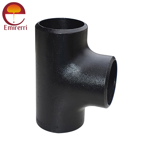
Product Description ANSI/ASME B16.9 Tee
ASME B16.9 is a standard developed by the American Society of Mechanical Engineers (ASME) for the design and manufacture of butt-welding fittings. Specifically, ASME B16.9 Tee refers to a type of pipe fitting that is used to join three sections of pipe together, typically at a right angle. It is designed to provide a “T” shape to allow flow from the main line to a branch pipe.
ANSI/ASME B16.9 Tee Dimension
| NOMINAL PIPE SIZE | OUTSIDE DIAMETER | CENTER TO END | LENGTH |
|---|---|---|---|
| Inch. | OD | C | M |
| 1/2 | 21.3 | 25 | 25 |
| 3/4 | 26.7 | 29 | 29 |
| 1 | 33.4 | 38 | 38 |
| 1 1/4 | 42.2 | 48 | 48 |
| 1 1/2 | 48.3 | 57 | 57 |
| 2 | 60.3 | 64 | 64 |
| 2 1/2 | 73 | 76 | 76 |
| 3 | 88.9 | 86 | 86 |
| 3 1/2 | 101.6 | 95 | 95 |
| 4 | 114.3 | 105 | 105 |
| 5 | 141.3 | 124 | 124 |
| 6 | 168.3 | 143 | 143 |
| 8 | 219.1 | 178 | 178 |
| 10 | 273.1 | 216 | 216 |
| 12 | 323.9 | 254 | 254 |
| 14 | 355.6 | 279 | 279 |
| 16 | 406.4 | 305 | 305 |
| 18 | 457.2 | 343 | 343 |
| 20 | 508 | 381 | 381 |
| 22 | 559 | 419 | 419 |
| 24 | 610 | 432 | 432 |
| 26 | 660 | 495 | 495 |
| 28 | 711 | 521 | 521 |
| 30 | 762 | 559 | 559 |
| 32 | 813 | 597 | 597 |
| 34 | 864 | 635 | 635 |
| 36 | 914 | 673 | 673 |
| 38 | 965 | 711 | 711 |
| 40 | 1016 | 749 | 749 |
| 42 | 1067 | 762 | 711 |
| 44 | 1118 | 813 | 762 |
| 46 | 1168 | 851 | 800 |
| 48 | 1219 | 889 | 838 |
ANSI/ASME B16.9 Tee Weight Chart
Equal Tee Weight Chart (in lbs)
Nominal Pipe Size (NPS) Schedule 40 Schedule 80 Schedule 160
1/2" 1.0 1.3 1.8
3/4" 1.4 1.8 2.5
1" 1.8 2.4 3.2
1 1/4" 2.3 3.0 4.0
1 1/2" 3.0 4.1 5.5
2" 4.2 6.2 8.3
2 1/2" 6.7 9.8 13.0
3" 9.4 14.1 18.7
4" 14.5 21.6 28.8
5" 19.0 28.3 37.7
6" 24.0 36.0 48.0
8" 34.0 51.0 68.0
10" 47.5 71.0 94.0
12" 60.0 90.0 120.0
14" 75.0 112.0 150.0
16" 94.0 141.0 188.0
18" 114.0 171.0 228.0
20" 134.0 201.0 268.0
24" 170.0 255.0 340.0
30" 255.0 382.5 510.0
36" 335.0 502.5 670.0
42" 420.0 630.0 840.0
48" 510.0 765.0 1020.0
Reducing Tee Weight Chart (in lbs)
Run x Branch Schedule 40 (lbs) Schedule 80 (lbs) Schedule 160 (lbs)
1/2" x 3/8" 0.3 0.4 0.6
3/4" x 1/2" 0.6 0.9 1.2
1" x 3/4" 0.8 1.2 1.6
1 1/4" x 1" 1.0 1.5 2.0
1 1/2" x 1" 1.2 1.8 2.5
2" x 1 1/2" 1.8 2.7 3.6
2 1/2" x 2" 2.5 3.8 5.1
3" x 2" 3.5 5.3 7.0
3" x 2 1/2" 3.8 5.7 7.6
4" x 3" 5.5 8.3 11.0
5" x 4" 7.3 10.9 14.4
6" x 4" 9.5 14.2 18.9
6" x 5" 10.1 15.1 20.2
8" x 6" 15.5 23.3 31.1
10" x 8" 21.0 31.5 42.0
12" x 10" 28.0 42.0 56.0
14" x 12" 36.0 54.0 72.0
16" x 12" 44.0 66.0 88.0
18" x 16" 56.0 84.0 112.0
20" x 16" 68.0 102.0 136.0
24" x 20" 96.0 144.0 192.0
24" x 10" 80.0 120.0 160.0
Tee Tolerance
Parameter Tolerance
Outside Diameter (OD) ±1% of nominal OD or ±0.5 mm, whichever is greater
Wall Thickness (WT) ±12.5% of specified wall thickness
Center-to-End Dimensions ±1.5% of nominal dimension or ±3 mm, whichever is greater
Branch Alignment ±2 mm for alignment between branch centerline and run centerline
Out-of-Roundness ≤1% of nominal OD
End Preparation ±1 mm for bevel length and ±2° for bevel angle
Surface Finish Free from defects such as cracks, dents, or visible seams
Marking Tolerance Legible and durable markings in accordance with ASME, ANSI, or applicable standards
Material
- Carbon Steel: ASTM A234 WPB, ASTM A105
- Alloy Steel: ASTM A234 WP9, WP11, WP22
- Stainless Steel: ASTM A403 WP304, WP316, WP321, WP347

Reviews
There are no reviews yet.