Welcome to Emirerri Steel Manufacturer Pvt Ltd
- About us
- Products
Pipe Fittings
- Hot-Rolled Steel Coils
- Cold-Rolled Steel Coils
- Galvanized Steel Coils
- Stainless Steel Coils
- Standard
- Blogs
- Quality
- Contact
- Download
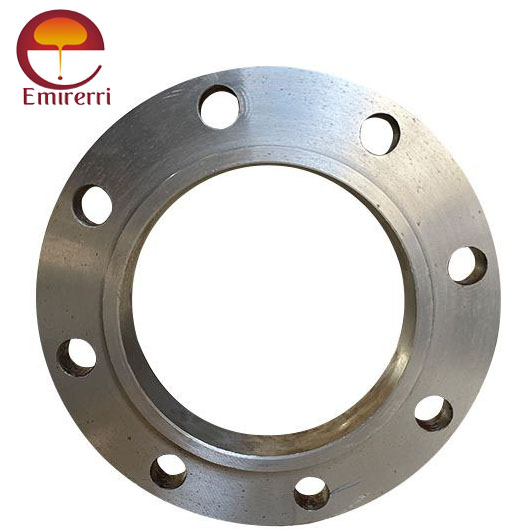
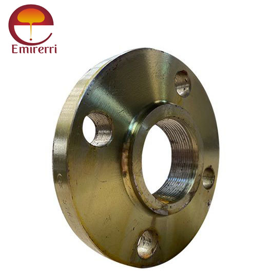
BS 4504 Flange refers to a series of flanges that are designed and manufactured according to the British Standard 4504. This standard is commonly used in the UK and other regions where British standards are adopted, and it outlines the dimensions, pressure ratings, and material requirements for flanges used in piping systems.


| Nominal Size (DN) | Nominal Pressure (PN) | Bolt Circle Diameter (D) | No. of Bolts (N) | Bolt Hole Diameter (d) | Flange Thickness (T) | Raised Face (RF) | Hub Length (L) | Flange Weight |
|---|---|---|---|---|---|---|---|---|
| DN 10 | PN 10, PN 16 | 70 mm | 4 | 10 mm | 12 mm | 2 mm | 20 mm | 0.35 kg |
| DN 15 | PN 10, PN 16 | 80 mm | 4 | 10 mm | 12 mm | 2 mm | 20 mm | 0.45 kg |
| DN 20 | PN 10, PN 16 | 90 mm | 4 | 10 mm | 12 mm | 2 mm | 20 mm | 0.55 kg |
| DN 25 | PN 10, PN 16 | 100 mm | 4 | 10 mm | 14 mm | 2 mm | 20 mm | 0.65 kg |
| DN 40 | PN 10, PN 16 | 120 mm | 8 | 12 mm | 16 mm | 2 mm | 30 mm | 1.1 kg |
| DN 50 | PN 10, PN 16 | 130 mm | 8 | 12 mm | 16 mm | 2 mm | 30 mm | 1.3 kg |
| DN 80 | PN 10, PN 16 | 150 mm | 8 | 12 mm | 18 mm | 2 mm | 30 mm | 1.8 kg |
| DN 100 | PN 10, PN 16 | 160 mm | 8 | 12 mm | 18 mm | 2 mm | 30 mm | 2.2 kg |
| DN 150 | PN 10, PN 16 | 190 mm | 12 | 16 mm | 20 mm | 3 mm | 40 mm | 3.4 kg |
| DN 200 | PN 10, PN 16 | 220 mm | 12 | 16 mm | 22 mm | 3 mm | 40 mm | 4.2 kg |
2025 © All rights reserved by Emirerri Steel Manufacturer Pvt Ltd