
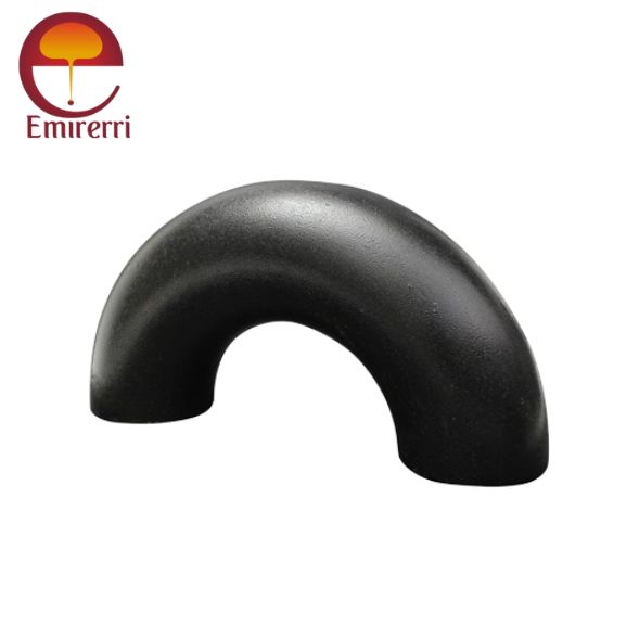
EN 10253-1 Elbow 45°, 90°, 180°
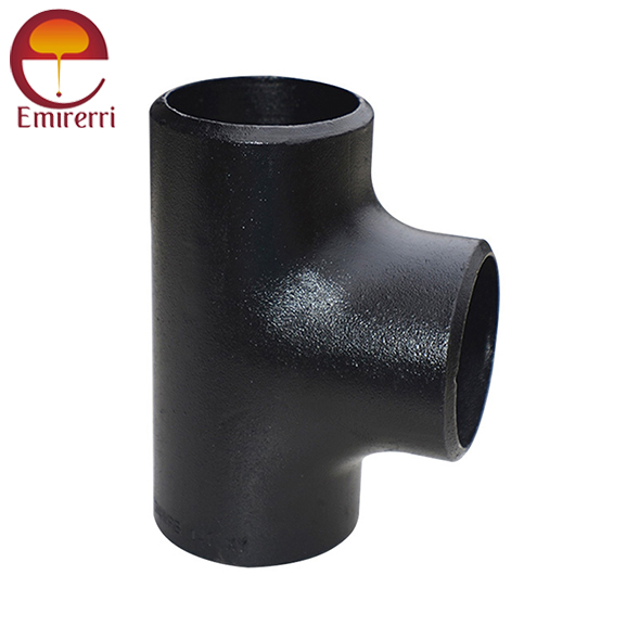
EN 10253-1 Tee Equal & Reducing
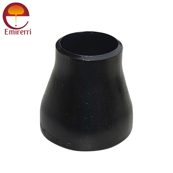
EN 10253-1 Reducer
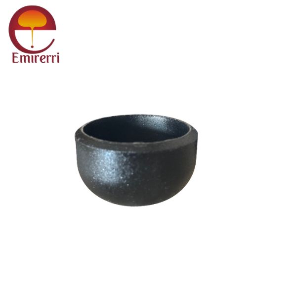
EN 10253-1 Cap

EN 10253-1 is a European standard that specifies the requirements for buttweld pipe fittings made from carbon steel and alloy steel. These fittings are commonly used in piping systems to change the flow direction, connect pipes of different sizes, or terminate a pipe. The standard ensures the fittings meet specific mechanical, chemical, and dimensional properties, making them suitable for use in demanding conditions.
NPS O.D.
D90 deg LR Center-to-End
A45 deg Long Radius Center-to-End B 90 deg 3D Center-to-End A 45 deg 3D Center-to-End B
1/2 21.3 38 16 – –
3/4 26.7 38 19 57 24
1 33.4 38 22 76 31
1¼ 42.2 48 25 95 39
1½ 48.3 57 29 114 47
2 60.3 76 35 152 63
2½ 73 95 44 190 79
3 88.9 114 51 229 95
3½ 101.6 133 57 267 111
4 114.3 152 64 305 127
5 141.3 190 79 381 157
6 168.3 229 95 457 189
8 219.1 305 127 610 252
10 273 381 159 762 316
12 323.8 457 190 914 378
14 355.6 533 222 1067 441
16 406.4 610 254 1219 505
18 457 686 286 1372 568
20 508 762 318 1524 632
22 559 838 343 1676 694
24 610 914 381 1829 757
26 660 991 406 1981 821
28 711 1067 438 2134 883
30 762 1143 470 2286 964
32 813 1219 502 2438 1010
34 864 1295 533 2591 1073
36 914 1372 565 2743 1135
38 965 1448 600 2896 1200
40 1016 1524 632 3048 1264
42 1067 1600 660 3200 1326
44 1118 1676 695 3353 1389
46 1168 1753 727 3505 1453
48 1219 1829 759 3658 1516
Inch. ND millimeter Center to center Radius Center to end Back to face
D O A B K
1/2 15 21,34 76,20 38,10 15,87 47,62
3/4 20 26,67 57,15 28,57 11,11 42,86
1 25 33,40 76,20 38,10 22,22 55,56
1 1/4 32 42,16 95,25 47,60 25,40 69,85
1 1/2 40 48,26 114,30 57,15 28,57 82,55
2 50 60,32 152,40 76,20 34,92 106,40
2 1/2 65 73,02 190,50 95,25 44,45 131,80
3 80 88,90 228,60 114,30 50,80 158,75
3 1/2 90 101,60 266,70 133,35 57,15 184,15
4 100 114,30 304,80 152,40 63,50 209,55
5 125 141,30 381,00 190,50 79,38 261,90
6 150 168,27 457,20 228,60 95,25 312,70
8 200 219,07 609,60 304,80 127,00 414,30
10 250 273,05 762,00 381,00 158,75 517,50
12 300 323,85 914,40 457,20 190,50 619,10
14 350 355,60 1066,80 533,40 222,25 711,20
16 400 406,40 1219,20 609,60 254,00 812,80
18 450 457,20 1371,60 685,80 285,74 914,40
20 500 508,00 1524,00 762,00 317,50 1016,00
22 550 558,80 1676,40 838,20 342,90 1117,60
24 600 609,60 1828,80 914,40 381,00 1219,20
28 700 711,20 2133,60 1066,80 441,90 1422,40
Normal Pipe Size Outside Daimeter
DASME 180 degree Long Rad ASME 180 degree Short Rad
Center to Center O Back to Face K Center to Center O Back to Face K
1/2 21.3 76 48 … …
3/4 26.7 76 51 … …
1 33.4 76 56 51 41
1.1/4 42.2 95 70 64 52
1.1/2 48.3 114 83 76 62
2 60.3 152 106 102 81
2.1/2 73 190 132 127 100
3 88.9 229 159 152 121
3.1/2 101.6 267 184 178 140
4 114.3 305 210 203 159
5 141.3 381 262 254 197
6 168.3 457 313 305 237
8 219.1 610 414 406 313
10 273 762 518 508 391
12 323.8 914 619 610 467
14 355.6 1067 711 711 533
16 406.4 1219 813 813 610
18 457 1372 914 914 686
20 508 1524 1016 1016 762
22 559 1676 1118 1118 838
24 610 1829 1219 1219 914
Normal Pipe Size Outside Daimeter D 180 degree Long Rad 180 degree Short Rad
Center to Center O Back to Face K Center to Center O Back to Face K
NOMINAL PIPE SIZE OUTSIDE DIAMETER CENTER TO END LENGTH
Inch. OD C M
1/2 21.3 25 25
3/4 26.7 29 29
1 33.4 38 38
1 1/4 42.2 48 48
1 1/2 48.3 57 57
2 60.3 64 64
2 1/2 73 76 76
3 88.9 86 86
3 1/2 101.6 95 95
4 114.3 105 105
5 141.3 124 124
6 168.3 143 143
8 219.1 178 178
10 273.1 216 216
12 323.9 254 254
14 355.6 279 279
16 406.4 305 305
18 457.2 343 343
20 508 381 381
22 559 419 419
24 610 432 432
26 660 495 495
28 711 521 521
30 762 559 559
32 813 597 597
34 864 635 635
36 914 673 673
38 965 711 711
40 1016 749 749
42 1067 762 711
44 1118 813 762
46 1168 851 800
48 1219 889 838
NOMINAL PIPE SIZE OUTSIDE DIAMETER CENTER TO END
Inch D P C M
1/2 x 3/8 21.3 17.1 25 25
1/2 x 1/4 21.3 13.7 25 25
3/4 x 1/2 26.7 21.3 29 29
3/4 x 3/8 26.7 17.1 29 29
1 x 3/4 33.4 26.7 38 38
1 x 1/2 33.4 21.3 38 38
1 1/4 x 1 42.2 33.4 48 48
1 1/4 x 3/4 42.2 26.7 48 48
1 1/4 x 1/2 42.2 21.3 48 48
1 1/2 x 1 1/2 48.3 42.2 57 57
1 1/2 x 1 48.3 33.4 57 57
1 1/2 x 3/4 48.3 26.7 57 57
1 1/2 x 1/2 48.3 21.3 57 57
2 x 1 1/2 60.3 48.2 64 60
2 x 1 1/4 60.3 42.2 64 57
2 x 1 60.3 33.4 64 51
2 x 3/4 60.3 26.7 64 44
2 1/2 x 2 73 60.3 76 70
2 1/2 x 1 1/2 73 48.3 76 67
2 1/2 x 1 1/4 73 42.2 76 64
2 1/2 x 1 73 33.4 76 57
3 x 2 1/2 88.9 73 86 83
3 x 2 88.9 60.3 86 76
3 x 1 1/2 88.9 48.3 86 73
3 x 1 1/4 88.9 42.2 86 70
3 1/2 x 3 101.6 88.9 95 92
3 1/2 x 21/2 101.6 73 95 89
3 1/2 x 2 101.6 60.3 95 83
3 1/2 x 1 1/2 101.6 48.3 95 79
4 x 3 1/2 114.3 101.6 105 102
4 x 3 114.3 88.9 105 98
4 x 2 1/2 114.3 73 105 95
4 x 2 114.3 60.3 105 89
4 x 1 1/2 114.3 48.3 105 86
5 x 4 141.3 114.3 124 117
5 x 3 1/2 141.3 101.6 124 114
5 x 3 141.3 88.9 124 111
5 x 2 1/2 141.3 73 124 108
5 x 2 141.3 60.3 124 105
6 x 5 168.3 141.3 143 137
6 x 4 168.3 114.3 143 130
6 x 3 1/2 168.3 101.6 143 127
6 x 3 168.3 88.9 143 124
6 x 2 1/2 168.3 73 143 121
8 x 6 219.1 168.3 178 168
8 x 5 219.1 141.3 178 162
8 x 4 219.1 114.3 178 156
8 x 3 1/2 219.1 101.6 178 152
10 x 8 273.1 219.1 216 203
10 x 6 273.1 168.1 216 194
10 x 5 273.1 141.3 216 191
10 x 4 273.1 114.3 216 184
12 x 10 323.9 273.1 254 241
12 x 8 323.9 219.1 254 229
12 x 6 323.9 168.3 254 219
12 x 5 323.9 141.3 254 216
14 x 12 355.6 323.9 279 270
14 x 10 355.6 273.1 279 257
14 x 8 355.6 219.1 279 248
14 x 6 355.6 168.3 279 238
16 x 14 406.4 355.6 305 305
16 x 12 406.4 323.9 305 295
16 x 10 406.4 273.1 305 283
16 x 8 406.4 219.1 305 273
16 x 6 406.4 168.3 305 264
18 x 16 457 406.4 343 330
18 x 14 457 355.6 343 330
18 x 12 457 323.9 343 321
18 x 10 457 273.1 343 308
18 x 8 457 219.1 343 298
20 x 18 508 457 381 368
20 x 16 508 406.4 381 356
20 x 14 508 355.6 381 356
20 x 12 508 323.9 381 346
20 x 10 508 273.1 381 333
20 x 8 508 219.1 381 324
22 x 20 559 508 419 406
22 x 18 559 457 419 394
22 x 16 559 406.4 419 381
22 x 14 559 355.6 419 381
22 x 12 559 323.9 419 371
24 x 10 559 273.1 419 359
24 x 22 610 559 432 432
24 x 20 610 508 432 432
24 x 18 610 457 432 419
24 x 16 610 406.4 432 406
24 x 14 610 355.6 432 406
24 x 12 610 323.9 432 397
24 x 10 610 273.1 432 384
NOMINAL PIPE SIZE OUTSIDE DIAMETER END TO END
Inch D P H
3/4 x 1/2 26.7 21.3 38
3/4 x 3/8 26.7 17.1 38
1 x 3/4 33.4 26.7 51
1 x 1/2 33.4 21.3 51
1 1/4 x 1 42.2 33.4 51
1 1/4 x 3/4 42.2 26.7 51
1 1/4 x 1/2 42.2 21.3 51
1 1/2 x 1 1/2 48.3 42.2 64
1 1/2 x 1 48.3 33.4 64
1 1/2 x 3/4 48.3 26.7 64
1 1/2 x 1/2 48.3 21.3 64
2 x 1 1/2 60.3 48.2 76
2 x 1 1/4 60.3 42.2 76
2 x 1 60.3 33.4 76
2 x 3/4 60.3 26.7 76
2 1/2 x 2 73 60.3 89
2 1/2 x 1 1/2 73 48.3 89
2 1/2 x 1 1/4 73 42.2 89
2 1/2 x 1 73 33.4 89
3 x 2 1/2 88.9 73 89
3 x 2 88.9 60.3 89
3 x 1 1/2 88.9 48.3 89
3 x 1 1/4 88.9 42.2 89
3 1/2 x 3 101.6 88.9 102
3 1/2 x 21/2 101.6 73 102
3 1/2 x 2 101.6 60.3 102
3 1/2 x 1 1/2 101.6 48.3 102
3 1/2 x 1 1/4 101.6 42.2 102
4 x 3 1/2 114.3 101.6 102
4 x 3 114.3 88.9 102
4 x 2 1/2 114.3 73 102
4 x 2 114.3 60.3 102
4 x 1 1/2 114.3 48.3 102
5 x 4 141.3 114.3 127
5 x 3 1/2 141.3 101.6 127
5 x 3 141.3 88.9 127
5 x 2 1/2 141.3 73 127
5 x 2 141.3 60.3 127
6 x 5 168.3 141.3 140
6 x 4 168.3 114.3 140
6 x 3 1/2 168.3 101.6 140
6 x 3 168.3 88.9 140
6 x 2 1/2 168.3 73 140
8 x 6 219.1 168.3 152
8 x 5 219.1 141.3 152
8 x 4 219.1 114.3 152
8 x 3 1/2 219.1 101.6 152
10 x 8 273.1 219.1 178
10 x 6 273.1 168.1 178
10 x 5 273.1 141.3 178
10 x 4 273.1 114.3 178
12 x 10 323.9 273.1 203
12 x 8 323.9 219.1 203
12 x 6 323.9 168.3 203
12 x 5 323.9 141.3 203
14 x 12 355.6 323.9 330
14 x 10 355.6 273.1 330
14 x 8 355.6 219.1 330
14 x 6 355.6 168.3 330
16 x 14 406.4 355.6 356
16 x 12 406.4 323.9 356
16 x 10 406.4 273.1 356
16 x 8 406.4 219.1 356
16 x 6 406.4 168.3 356
18 x 16 457 406.4 381
18 x 14 457 355.6 381
18 x 12 457 323.9 381
18 x 10 457 273.1 381
18 x 8 457 219.1 381
20 x 18 508 457 508
20 x 16 508 406.4 508
20 x 14 508 355.6 508
20 x 12 508 323.9 508
20 x 10 508 273.1 508
20 x 8 508 219.1 508
22 x 20 559 508 508
22 x 18 559 457 508
22 x 16 559 406.4 508
22 x 14 559 355.6 508
22 x 12 559 323.9 508
24 x 10 559 273.1 508
24 x 22 610 559 508
24 x 20 610 508 508
24 x 18 610 457 508
24 x 16 610 406.4 508
24 x 14 610 355.6 508
24 x 12 610 323.9 508
24 x 10 610 273.1 508
Inch. MM Height
D E
1/2 15 21,34 25,40
3/4 20 26,67 31,75
25 33,40 38,10
1 1/4 32 42,16 38,10
1 1/2 40 48,26 38,10
2 50 60,32 38,10
2 1/2 65 73,02 38,10
3 80 88,90 50,80
3 1/2 90 101,60 63,50
4 100 114,30 63,50
5 125 141,30 76,20
6 150 168,27 88,90
8 200 219,07 101,60
10 250 273,05 127,00
12 300 323,85 152,40
14 350 355,60 165,10
16 400 406,40 177,80
18 450 457,20 203,20
20 500 508,00 228,60
22 550 558,80 254,00
24 600 609,60 266,70
28 700 711,20 266,70
NOMINAL PIPE SIZE LAP DIAMETER OUTSIDE DIAMETER LONG PATTERN LENGTH SHORT PATTERN LENGTH RADIUS
Inch. A OD Min OD Max L L R
1/2 35 22.8 20.5 76 51 3
3/4 43 28.1 25.9 76 51 3
1 51 35 32.6 102 51 3
1 1/4 64 43.6 41.4 102 51 5
1 1/2 73 49.9 47.5 102 51 6
2 92 62.4 59.5 152 64 8
2 1/2 105 75.3 72.2 152 64 8
3 127 91.3 88.1 152 64 10
3 1/2 140 104 100.8 152 76 10
4 157 116.7 113.5 152 76 11
5 186 144.3 140.5 203 76 11
6 216 171.3 167.5 203 89 13
8 270 222.1 218.3 203 102 13
10 324 277.2 272.3 254 127 13
12 381 328 323.1 254 152 13
14 413 359.9 354.8 305 152 13
16 470 411 405.6 305 152 13
18 533 462 456 305 152 13
20 584 514 507 305 152 13
22 641 565 558 305 152 13
24 692 616 609 305 152 13
Nominal Pipe Size (NPS) Schedule 40 Schedule 80 Schedule 160
1/2″ 0.6 0.9 1.3
3/4″ 0.8 1.2 1.7
1″ 1.1 1.6 2.2
1 1/4″ 1.4 2.1 3.0
1 1/2″ 1.8 2.7 3.7
2″ 2.6 4.0 5.5
2 1/2″ 4.1 6.2 8.4
3″ 5.7 8.6 11.5
4″ 8.6 12.7 17.0
5″ 11.3 17.0 22.7
6″ 14.5 21.8 29.5
8″ 20.5 30.7 41.0
10″ 28.0 42.0 56.0
12″ 36.8 55.2 73.5
14″ 48.3 72.4 96.5
16″ 60.5 90.7 120.5
18″ 74.4 111.6 148.0
20″ 89.9 134.9 179.5
24″ 114.0 171.0 228.0
30″ 162.0 243.0 324.0
36″ 212.0 318.0 424.0
42″ 274.0 411.0 548.0
48″ 352.0 528.0 704.0
Nominal Pipe Size (NPS) Schedule 40 Schedule 80 Schedule 160
1/2″ 0.7 1.0 1.4
3/4″ 1.0 1.4 2.0
1″ 1.3 1.9 2.6
1 1/4″ 1.6 2.4 3.3
1 1/2″ 2.1 3.0 4.0
2″ 2.9 4.4 5.9
2 1/2″ 4.5 6.8 9.1
3″ 6.5 9.7 12.9
4″ 9.7 14.6 19.5
5″ 12.7 19.0 25.3
6″ 16.5 24.8 33.0
8″ 23.0 34.5 46.0
10″ 31.5 47.3 63.7
12″ 40.9 61.4 81.9
14″ 53.1 79.7 106.0
16″ 66.0 99.0 132.0
18″ 80.7 121.0 160.0
20″ 97.5 146.0 194.0
24″ 123.5 185.0 246.0
30″ 177.0 265.5 354.0
36″ 234.0 351.0 468.0
42″ 304.0 456.0 608.0
48″ 388.0 582.0 776.0
Nominal Pipe Size (NPS) Schedule 40 Schedule 80 Schedule 160
1/2″ 1.1 1.5 2.0
3/4″ 1.4 2.0 2.8
1″ 1.8 2.7 3.6
1 1/4″ 2.3 3.4 4.5
1 1/2″ 3.0 4.4 5.9
2″ 4.3 6.4 8.5
2 1/2″ 6.7 10.1 13.4
3″ 9.4 14.1 18.7
4″ 14.0 20.9 27.8
5″ 18.5 27.5 36.7
6″ 24.0 35.8 47.8
8″ 33.0 49.5 66.0
10″ 44.5 66.8 89.0
12″ 56.0 84.0 112.0
14″ 71.0 106.5 142.0
16″ 88.0 132.0 176.0
18″ 108.0 162.0 216.0
20″ 128.0 192.0 256.0
24″ 160.0 240.0 320.0
Nominal Pipe Size (NPS) Schedule 40 Schedule 80 Schedule 160
1/2″ 1.0 1.3 1.8
3/4″ 1.4 1.8 2.5
1″ 1.8 2.4 3.2
1 1/4″ 2.3 3.0 4.0
1 1/2″ 3.0 4.1 5.5
2″ 4.2 6.2 8.3
2 1/2″ 6.7 9.8 13.0
3″ 9.4 14.1 18.7
4″ 14.5 21.6 28.8
5″ 19.0 28.3 37.7
6″ 24.0 36.0 48.0
8″ 34.0 51.0 68.0
10″ 47.5 71.0 94.0
12″ 60.0 90.0 120.0
14″ 75.0 112.0 150.0
16″ 94.0 141.0 188.0
18″ 114.0 171.0 228.0
20″ 134.0 201.0 268.0
24″ 170.0 255.0 340.0
30″ 255.0 382.5 510.0
36″ 335.0 502.5 670.0
42″ 420.0 630.0 840.0
48″ 510.0 765.0 1020.0
Run x Branch Schedule 40 (lbs) Schedule 80 (lbs) Schedule 160 (lbs)
1/2″ x 3/8″ 0.3 0.4 0.6
3/4″ x 1/2″ 0.6 0.9 1.2
1″ x 3/4″ 0.8 1.2 1.6
1 1/4″ x 1″ 1.0 1.5 2.0
1 1/2″ x 1″ 1.2 1.8 2.5
2″ x 1 1/2″ 1.8 2.7 3.6
2 1/2″ x 2″ 2.5 3.8 5.1
3″ x 2″ 3.5 5.3 7.0
3″ x 2 1/2″ 3.8 5.7 7.6
4″ x 3″ 5.5 8.3 11.0
5″ x 4″ 7.3 10.9 14.4
6″ x 4″ 9.5 14.2 18.9
6″ x 5″ 10.1 15.1 20.2
8″ x 6″ 15.5 23.3 31.1
10″ x 8″ 21.0 31.5 42.0
12″ x 10″ 28.0 42.0 56.0
14″ x 12″ 36.0 54.0 72.0
16″ x 12″ 44.0 66.0 88.0
18″ x 16″ 56.0 84.0 112.0
20″ x 16″ 68.0 102.0 136.0
24″ x 20″ 96.0 144.0 192.0
24″ x 10″ 80.0 120.0 160.0
Run x Branch Schedule 40 (lbs) Schedule 80 (lbs) Schedule 160 (lbs)
3/4″ x 1/2″ 0.6 0.8 1.0
1″ x 3/4″ 1.0 1.4 1.8
1 1/4″ x 1″ 1.4 2.0 2.6
1 1/2″ x 1″ 1.6 2.4 3.2
2″ x 1 1/2″ 2.3 3.2 4.3
2 1/2″ x 2″ 3.0 4.4 5.9
3″ x 2″ 4.2 6.1 8.2
3″ x 2 1/2″ 4.4 6.5 8.7
4″ x 3″ 6.1 9.1 12.2
5″ x 4″ 8.3 12.5 16.7
6″ x 4″ 10.3 15.5 20.7
6″ x 5″ 11.0 16.5 22.0
8″ x 6″ 16.3 24.5 32.7
10″ x 8″ 22.0 33.0 44.0
12″ x 10″ 28.6 43.0 57.3
14″ x 12″ 37.6 56.4 75.2
16″ x 12″ 46.6 69.9 93.2
18″ x 16″ 59.0 88.5 118.0
20″ x 16″ 71.0 106.5 142.0
24″ x 20″ 98.0 147.0 196.0
24″ x 10″ 78.0 117.0 156.0
Nominal Pipe Size (NPS) Schedule 40 (lbs) Schedule 80 (lbs) Schedule 160 (lbs)
1/2″ 0.16 0.23 0.30
3/4″ 0.23 0.32 0.42
1″ 0.30 0.45 0.60
1 1/4″ 0.40 0.60 0.80
1 1/2″ 0.50 0.75 1.00
2″ 0.70 1.05 1.40
2 1/2″ 1.05 1.60 2.10
3″ 1.40 2.10 2.80
4″ 2.00 3.00 4.00
5″ 2.70 4.00 5.30
6″ 3.50 5.20 7.00
8″ 5.00 7.50 10.00
10″ 7.50 11.20 14.90
12″ 10.00 15.00 20.00
14″ 12.50 18.70 25.00
16″ 15.50 23.30 31.00
18″ 19.00 28.50 38.00
20″ 23.00 34.50 46.00
24″ 30.00 45.00 60.00
28″ 37.50 56.00 75.00
Nominal Pipe Size (NPS) D1 (Outside Diameter) D2 (Diameter of Stub End) L (Length) B (Flange Thickness)
1/2″ 0.840 0.625 1.38 0.125
3/4″ 1.050 0.875 1.50 0.125
1″ 1.315 1.050 1.75 0.125
1 1/4″ 1.660 1.375 2.00 0.125
1 1/2″ 1.900 1.500 2.25 0.125
2″ 2.375 2.000 2.50 0.125
2 1/2″ 2.875 2.500 2.75 0.125
3″ 3.500 3.000 3.00 0.125
4″ 4.500 3.500 3.50 0.125
5″ 5.563 4.500 4.00 0.125
6″ 6.625 5.500 4.50 0.125
8″ 8.625 7.000 5.00 0.125
10″ 10.750 8.625 5.50 0.125
12″ 12.750 10.750 6.00 0.125
14″ 14.000 12.750 6.50 0.125
16″ 16.000 14.000 7.00 0.125
18″ 18.000 16.000 7.50 0.125
20″ 20.000 18.000 8.00 0.125
24″ 24.000 22.000 8.50 0.125
28″ 28.000 26.000 9.00 0.125
Parameter Tolerance
Angle ±1° for all angles (45°, 90°, 180°)
Outside Diameter (OD) ±1% of nominal OD or ±0.5 mm, whichever is greater
Wall Thickness (WT) ±12.5% of specified wall thickness
Center-to-End Dimensions ±1.5% of the nominal dimension or ±3 mm, whichever is greater
Out-of-Roundness ≤1% of the nominal OD
End Preparation ±1 mm for length and ±2° for bevel angle
Surface Finish Free from defects such as cracks, dents, or visible seams
Marking Tolerance Legible and durable markings in accordance with ASME, ANSI, or applicable standards
Parameter Tolerance
Outside Diameter (OD) Large End: ±1% of nominal OD or ±0.5 mm (whichever is greater)
Small End: ±1% of nominal OD or ±0.5 mm (whichever is greater)
Wall Thickness (WT) ±12.5% of specified wall thickness
Reducer Length (L) ±1.5% of the nominal length or ±3 mm (whichever is greater)
Concentricity Offset ≤5% of the nominal OD at the small end (for concentric reducers)
Eccentricity Offset ≤5% of the nominal OD at the small end (for eccentric reducers)
End Preparation ±1 mm for bevel length and ±2° for bevel angle
Out-of-Roundness ≤1% of nominal OD at both ends
Surface Finish Free from defects such as cracks, dents, or visible seams
Marking Tolerance Legible and durable markings in accordance with ASME, ANSI, or applicable standards
Parameter Tolerance
Outside Diameter (OD) ±1% of nominal OD or ±0.5 mm, whichever is greater
Wall Thickness (WT) ±12.5% of specified wall thickness
Center-to-End Dimensions ±1.5% of nominal dimension or ±3 mm, whichever is greater
Branch Alignment ±2 mm for alignment between branch centerline and run centerline
Out-of-Roundness ≤1% of nominal OD
End Preparation ±1 mm for bevel length and ±2° for bevel angle
Surface Finish Free from defects such as cracks, dents, or visible seams
Marking Tolerance Legible and durable markings in accordance with ASME, ANSI, or applicable standards
Parameter Tolerance
Outside Diameter (OD) ±1% of nominal OD or ±0.5 mm, whichever is greater
Wall Thickness (WT) ±12.5% of specified wall thickness
Height (H) ±1.5% of the nominal height or ±3 mm, whichever is greater
Out-of-Roundness ≤1% of the nominal OD
End Preparation ±1 mm for bevel length and ±2° for bevel angle
Surface Finish Free from defects such as cracks, dents, or visible seams
Marking Tolerance Legible and durable markings in accordance with ASME, ANSI, or applicable standards
Outside Diameter (OD): There are specific tolerances on the outside diameter of fittings. These tolerances ensure that the fitting can be properly welded into the pipework without issues.
Wall Thickness: Wall thickness tolerances are provided to ensure that the fitting’s strength is consistent and adequate for the intended pressure and service conditions.
Length: The length of fittings, such as elbows and reducers, will also have specific tolerances to ensure the correct overall dimensions for installation.
Angular Tolerances: Fittings such as elbows and tees have specific tolerances for angular deviation. This ensures that the fittings meet the required angles and align correctly when assembled.
Radius and Bend Radii:
For elbows and other curved fittings, there are tolerances on the bend radius, ensuring that the curve is within acceptable limits for both strength and fit.
Surface Finish Tolerances: Certain tolerance requirements may also apply to the surface finish of the fittings to ensure that they do not have defects that could affect their performance, especially in applications where they will undergo high pressure or high temperature.
2025 © All rights reserved by Emirerri Steel Manufacturer.