A steel elbow is a pipe fitting used to connect two lengths of pipe or tube, allowing for a change in the direction of the flow within the piping system. The change in direction is typically 45°, 90°, or 180°, but custom angles can also be manufactured to meet specific requirements. Steel elbows are made from various materials, including carbon steel, stainless steel, and alloy steel, depending on the application and environmental conditions.
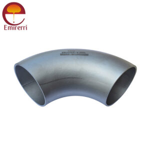
Stainless Steel 90 Degree Elbow
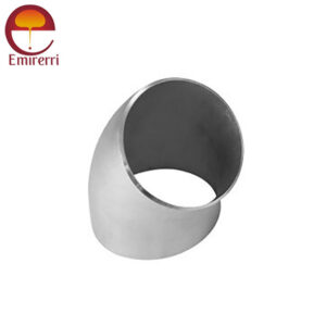
Stainless Steel 45 Degree Elbow
Stainless Steel 180 Degree Elbow
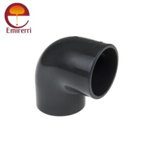
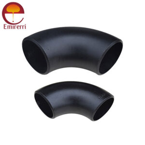
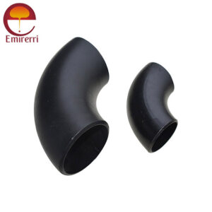
Carbon Steel 90 Degree Elbow
Carbon Steel 45 Degree Elbow
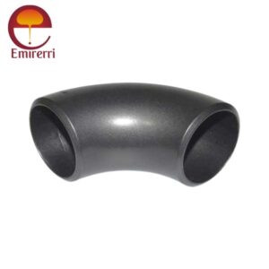
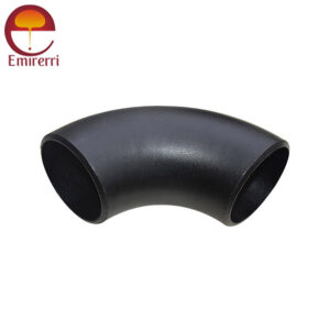
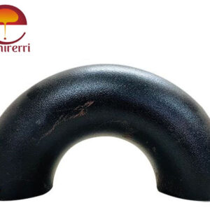
Carbon Steel 180 Degree Elbow
Steel Elbow Dimension
45-Degree Elbow Dimensions Chart (in lbs)
NPS
O.D.
D
90 deg LR Center-to-End
A
45 deg Long Radius Center-to-End B
90 deg 3D Center-to-End A
45 deg 3D Center-to-End B
1/2
21.3
38
16
–
–
3/4
26.7
38
19
57
24
1
33.4
38
22
76
31
1¼
42.2
48
25
95
39
1½
48.3
57
29
114
47
2
60.3
76
35
152
63
2½
73
95
44
190
79
3
88.9
114
51
229
95
3½
101.6
133
57
267
111
4
114.3
152
64
305
127
5
141.3
190
79
381
157
6
168.3
229
95
457
189
8
219.1
305
127
610
252
10
273
381
159
762
316
12
323.8
457
190
914
378
14
355.6
533
222
1067
441
16
406.4
610
254
1219
505
18
457
686
286
1372
568
20
508
762
318
1524
632
22
559
838
343
1676
694
24
610
914
381
1829
757
26
660
991
406
1981
821
28
711
1067
438
2134
883
30
762
1143
470
2286
964
32
813
1219
502
2438
1010
34
864
1295
533
2591
1073
36
914
1372
565
2743
1135
38
965
1448
600
2896
1200
40
1016
1524
632
3048
1264
42
1067
1600
660
3200
1326
44
1118
1676
695
3353
1389
46
1168
1753
727
3505
1453
48
1219
1829
759
3658
1516
90 Degree Elbow Dimensions Chart (in lbs)
Inch.
ND
millimeter
Center to center
Radius
Center to end
Back to face
D
O
A
B
K
1/2
15
21,34
76,20
38,10
15,87
47,62
3/4
20
26,67
57,15
28,57
11,11
42,86
1
25
33,40
76,20
38,10
22,22
55,56
1 1/4
32
42,16
95,25
47,60
25,40
69,85
1 1/2
40
48,26
114,30
57,15
28,57
82,55
2
50
60,32
152,40
76,20
34,92
106,40
2 1/2
65
73,02
190,50
95,25
44,45
131,80
3
80
88,90
228,60
114,30
50,80
158,75
3 1/2
90
101,60
266,70
133,35
57,15
184,15
4
100
114,30
304,80
152,40
63,50
209,55
5
125
141,30
381,00
190,50
79,38
261,90
6
150
168,27
457,20
228,60
95,25
312,70
8
200
219,07
609,60
304,80
127,00
414,30
10
250
273,05
762,00
381,00
158,75
517,50
12
300
323,85
914,40
457,20
190,50
619,10
14
350
355,60
1066,80
533,40
222,25
711,20
16
400
406,40
1219,20
609,60
254,00
812,80
18
450
457,20
1371,60
685,80
285,74
914,40
20
500
508,00
1524,00
762,00
317,50
1016,00
22
550
558,80
1676,40
838,20
342,90
1117,60
24
600
609,60
1828,80
914,40
381,00
1219,20
28
700
711,20
2133,60
1066,80
441,90
1422,40
180 Degree Elbow Dimensions Chart (in lbs)
Normal Pipe Size
Outside Daimeter
D
ASME 180 degree Long Rad
ASME 180 degree Short Rad
Center to Center O
Back to Face K
Center to Center O
Back to Face K
1/2
21.3
76
48
…
…
3/4
26.7
76
51
…
…
1
33.4
76
56
51
41
1.1/4
42.2
95
70
64
52
1.1/2
48.3
114
83
76
62
2
60.3
152
106
102
81
2.1/2
73
190
132
127
100
3
88.9
229
159
152
121
3.1/2
101.6
267
184
178
140
4
114.3
305
210
203
159
5
141.3
381
262
254
197
6
168.3
457
313
305
237
8
219.1
610
414
406
313
10
273
762
518
508
391
12
323.8
914
619
610
467
14
355.6
1067
711
711
533
16
406.4
1219
813
813
610
18
457
1372
914
914
686
20
508
1524
1016
1016
762
22
559
1676
1118
1118
838
24
610
1829
1219
1219
914
Normal Pipe Size
Outside Daimeter D
180 degree Long Rad
180 degree Short Rad
Center to Center O
Back to Face K
Center to Center O
Back to Face K
Steel Elbow Weight Chart
45-degree Elbow Weight Chart (in lbs)
Nominal Pipe Size (NPS)
Schedule 40
Schedule 80
Schedule 160
1/2″
0.6
0.9
1.3
3/4″
0.8
1.2
1.7
1″
1.1
1.6
2.2
1 1/4″
1.4
2.1
3.0
1 1/2″
1.8
2.7
3.7
2″
2.6
4.0
5.5
2 1/2″
4.1
6.2
8.4
3″
5.7
8.6
11.5
4″
8.6
12.7
17.0
5″
11.3
17.0
22.7
6″
14.5
21.8
29.5
8″
20.5
30.7
41.0
10″
28.0
42.0
56.0
12″
36.8
55.2
73.5
14″
48.3
72.4
96.5
16″
60.5
90.7
120.5
18″
74.4
111.6
148.0
20″
89.9
134.9
179.5
24″
114.0
171.0
228.0
30″
162.0
243.0
324.0
36″
212.0
318.0
424.0
42″
274.0
411.0
548.0
48″
352.0
528.0
704.0
90-degree Elbow Weight Chart (in lbs)
Nominal Pipe Size (NPS)
Schedule 40
Schedule 80
Schedule 160
1/2″
0.7
1.0
1.4
3/4″
1.0
1.4
2.0
1″
1.3
1.9
2.6
1 1/4″
1.6
2.4
3.3
1 1/2″
2.1
3.0
4.0
2″
2.9
4.4
5.9
2 1/2″
4.5
6.8
9.1
3″
6.5
9.7
12.9
4″
9.7
14.6
19.5
5″
12.7
19.0
25.3
6″
16.5
24.8
33.0
8″
23.0
34.5
46.0
10″
31.5
47.3
63.7
12″
40.9
61.4
81.9
14″
53.1
79.7
106.0
16″
66.0
99.0
132.0
18″
80.7
121.0
160.0
20″
97.5
146.0
194.0
24″
123.5
185.0
246.0
30″
177.0
265.5
354.0
36″
234.0
351.0
468.0
42″
304.0
456.0
608.0
48″
388.0
582.0
776.0
180 Degree Elbow Weight Chart (in lbs)
Nominal Pipe Size (NPS)
Schedule 40
Schedule 80
Schedule 160
1/2″
1.1
1.5
2.0
3/4″
1.4
2.0
2.8
1″
1.8
2.7
3.6
1 1/4″
2.3
3.4
4.5
1 1/2″
3.0
4.4
5.9
2″
4.3
6.4
8.5
2 1/2″
6.7
10.1
13.4
3″
9.4
14.1
18.7
4″
14.0
20.9
27.8
5″
18.5
27.5
36.7
6″
24.0
35.8
47.8
8″
33.0
49.5
66.0
10″
44.5
66.8
89.0
12″
56.0
84.0
112.0
14″
71.0
106.5
142.0
16″
88.0
132.0
176.0
18″
108.0
162.0
216.0
20″
128.0
192.0
256.0
24″
160.0
240.0
320.0
Types of Steel Elbows
1. Based on Angle
45° Elbow: Used to make a 45-degree turn in the piping system.
90° Elbow: Commonly used for a right-angle turn.
180° Elbow: Allows for a complete reversal of flow direction.
2. Based on Radius
Short Radius (SR) Elbow: The radius of curvature is equal to the nominal diameter of the pipe. Ideal for compact systems with space constraints.
Long Radius (LR) Elbow: The radius of curvature is 1.5 times the nominal diameter of the pipe. Preferred for systems requiring smoother flow and minimal pressure drop.
3. Based on the Connection Type
Buttweld Elbow: Welded directly to the pipe for a secure and leak-proof connection.
Socket Weld Elbow: Features a socket into which the pipe is inserted before welding.
Threaded Elbow: Equipped with threads for screw-on connections, commonly used in smaller pipelines.
Flanged Elbow: Comes with flanges for bolted connections, making it easier to assemble and disassemble.
4. Based on Material
Carbon Steel Elbow: Suitable for high-pressure and high-temperature applications.
Alloy Steel Elbow: Provides enhanced mechanical properties for specialized applications.
Duplex and Super Duplex Steel Elbow: Combines strength and corrosion resistance for demanding industries.
Manufacturing Processes
1. Mandrel Method
The mandrel method involves heating a straight steel pipe and shaping it into an elbow using a mandrel and dies. This process ensures uniform wall thickness and smooth surface finish.
2. Hot Forming
In hot forming, a steel billet is heated to high temperatures and shaped into an elbow using a die. The high-temperature process improves the mechanical properties of the elbow.
3. Cold Forming
Cold forming involves shaping the elbow without heating, using high-pressure hydraulic machines. This method is suitable for producing small-diameter elbows with high precision.
4. Extrusion
The extrusion process pushes a heated steel billet through a die to create the elbow. It’s commonly used for high-strength and large-diameter elbows.
5. Welding and Fabrication
Welding multiple steel segments together creates elbows for unique configurations and large diameters. This method is used when standard sizes and shapes don’t meet the project requirements.
Benefits of Steel Elbows
1. Durability and Strength
Steel elbows are known for their robust construction, making them suitable for high-pressure and high-temperature environments.
2. Corrosion Resistance
Stainless steel and specialized alloys offer exceptional resistance to corrosion, ensuring longevity in harsh environments.
3. Versatility
Available in various angles, radii, and connection types, steel elbows can be customized to suit any application.
4. Ease of Installation
Threaded and flanged elbows simplify installation and maintenance, especially in complex systems.
5. Cost-Effectiveness
Steel elbows provide a long-term solution due to their durability, reducing the need for frequent replacements.