

Description
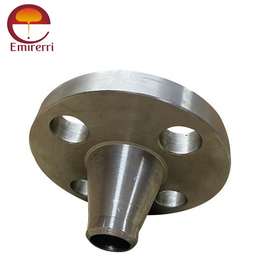
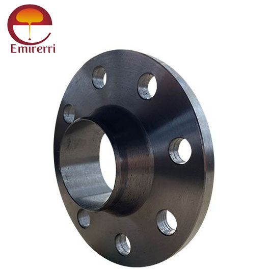
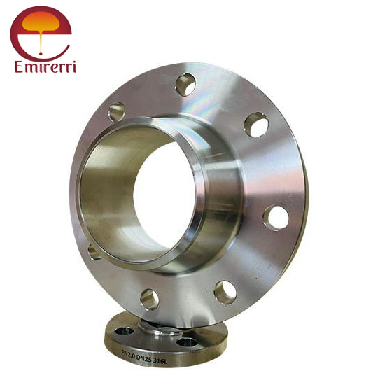
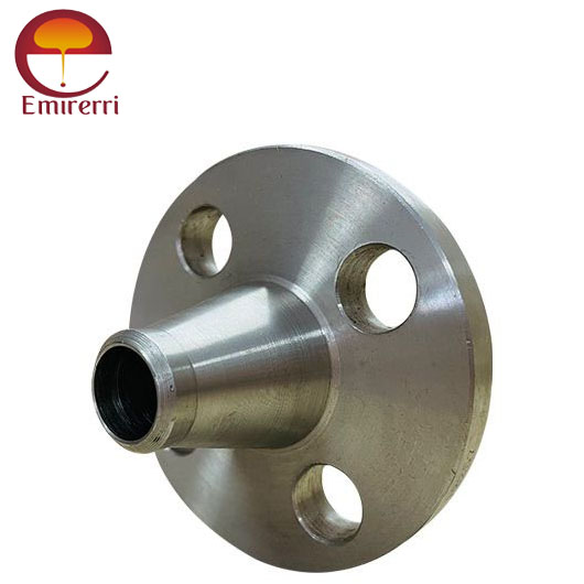
Product Description DIN EN 1092-1 Weld Neck Flange
DIN EN 1092-1 Weld Neck Flange is a widely used component in industrial piping systems, designed to ensure secure and durable connections for high-pressure applications. This flange standard, established by the European Union, specifies the dimensions, pressure ratings, and material requirements for Weld Neck Flanges in various industries such as oil and gas, chemical processing, power generation, and water treatment.
DIN EN 1092-1 is a European standard that specifies the dimensions and requirements for flanges, including the Weld Neck Flange. A Weld Neck Flange, also known as a Type 11 flange, is widely used in high-pressure and high-temperature applications due to its strong and robust design. It is characterized by a long tapered neck that is welded to the pipe, offering high strength and resistance to stress concentrations.
The primary feature of the DIN EN 1092-1 Weld Neck Flange is its long, tapered neck, which provides a smooth transition from the flange to the pipe. This design helps evenly distribute stresses, preventing stress concentrations that could lead to leaks or failures under high-pressure conditions. The neck allows for easy welding, ensuring a strong, leak-proof joint.
DIN EN 1092-1 Weld Neck Flanges are available in a wide range of sizes and materials, including carbon steel, stainless steel, and various alloys. These materials are selected for their excellent corrosion resistance, strength, and durability, ensuring a long service life in demanding environments. The flange standard offers different pressure classes, making it suitable for both low and high-pressure applications.
DIN EN 1092-1 Weld Neck Flange Dimension
Class 150 Weld Neck Flange Dimensions
| Size in Inch | Size in mm | Outer Diameter | Flange Thickness | Hub OD | Weld Neck OD | Welding Neck Length | Bore | RF Diameter | RF Height | PCD | Weld Face |
|---|---|---|---|---|---|---|---|---|---|---|---|
| A | B | C | D | E | F | G | H | I | J | ||
| 1/2 | 15 | 90 | 9.6 | 30 | 21.3 | 46 | 34.9 | 2 | 60.3 | 1.6 | |
| 3/4 | 20 | 100 | 11.2 | 38 | 26.7 | 51 | 42.9 | 2 | 69.9 | 1.6 | |
| 1 | 25 | 110 | 12.7 | 49 | 33.4 | 54 | 50.8 | 2 | 79.4 | 1.6 | |
| 1 1/4 | 32 | 115 | 14.3 | 59 | 42.2 | 56 | 63.5 | 2 | 88.9 | 1.6 | |
| 1 1/2 | 40 | 125 | 15.9 | 65 | 48.3 | 60 | 73 | 2 | 98.4 | 1.6 | |
| 2 | 50 | 150 | 17.5 | 78 | 60.3 | 62 | 92.1 | 2 | 120.7 | 1.6 | |
| 2 1/2 | 65 | 180 | 20.7 | 90 | 73 | 68 | 104.8 | 2 | 139.7 | 1.6 | |
| 3 | 80 | 190 | 22.3 | 108 | 88.9 | 68 | 127 | 2 | 152.4 | 1.6 | |
| 3 1/2 | 90 | 215 | 22.3 | 122 | 101.6 | 70 | Welding Neck bore is derived from the pipe schedule | 139.7 | 2 | 177.8 | 1.6 |
| 4 | 100 | 230 | 22.3 | 135 | 114.3 | 75 | 157.2 | 2 | 190.5 | 1.6 | |
| 5 | 125 | 255 | 22.3 | 164 | 141.3 | 87 | 185.7 | 2 | 215.9 | 1.6 | |
| 6 | 150 | 280 | 23.9 | 192 | 168.3 | 87 | 215.9 | 2 | 241.3 | 1.6 | |
| 8 | 200 | 345 | 27 | 246 | 219.1 | 100 | 269.9 | 2 | 298.5 | 1.6 | |
| 10 | 250 | 405 | 28.6 | 305 | 273 | 100 | 323.8 | 2 | 362 | 1.6 | |
| 12 | 300 | 485 | 30.2 | 365 | 323.8 | 113 | 381 | 2 | 431.8 | 1.6 | |
| 14 | 350 | 535 | 33.4 | 400 | 355.6 | 125 | 412.8 | 2 | 476.3 | 1.6 | |
| 16 | 400 | 595 | 35 | 457 | 406.4 | 125 | 469.9 | 2 | 539.8 | 1.6 | |
| 18 | 450 | 635 | 38.1 | 505 | 457.2 | 138 | 533.4 | 2 | 577.9 | 1.6 | |
| 20 | 500 | 700 | 41.3 | 559 | 508 | 143 | 584.2 | 2 | 635 | 1.6 | |
| 24 | 600 | 815 | 46.1 | 663 | 610 | 151 | 692.2 | 2 | 749.3 | 1.6 |
Class 150 Weld Neck Flange Stud & Bolt Dimensions
Size in Inch Size in mm Outer Diameter Flange Thickness Hub OD Weld Neck OD Welding Neck Length Bore RF Diameter RF Height PCD Weld Face A B C D E F G H I J 1/2 15 95 12.7 38 21.3 51 34.9 2 66.7 1.6 3/4 20 115 14.3 48 26.7 56 42.9 2 82.6 1.6 1 25 125 15.9 54 33.4 60 50.8 2 88.9 1.6 1 1/4 32 135 17.5 64 42.2 64 63.5 2 98.4 1.6 1 1/2 40 155 19.1 70 48.3 67 73 2 114.3 1.6 2 50 165 20.7 84 60.3 68 92.1 2 127 1.6 2 1/2 65 190 23.9 100 73 75 104.8 2 149.2 1.6 3 80 210 27 117 88.9 78 127 2 168.3 1.6 3 1/2 90 230 28.6 133 101.6 79 Welding Neck bore is derived from the pipe schedule 139.7 2 184.2 1.6 4 100 255 30.2 146 114.3 84 157.2 2 200 1.6 5 125 280 33.4 178 141.3 97 185.7 2 235 1.6 6 150 320 35 206 168.3 97 215.9 2 269.9 1.6 8 200 380 39.7 260 219.1 110 269.9 2 330.2 1.6 10 250 445 46.1 321 273 116 323.8 2 387.4 1.6 12 300 520 49.3 375 323.8 129 381 2 450.8 1.6 14 350 585 52.4 425 355.6 141 412.8 2 514.4 1.6 16 400 650 55.6 483 406.4 144 469.9 2 571.5 1.6 18 450 710 58.8 533 457 157 533.4 2 628.6 1.6 20 500 775 62 587 508 160 584.2 2 685.8 1.6 24 600 915 68.3 702 610 167 692.2 2 812.8 1.6
Class 300 Weld Neck Flange Stud & Bolt Dimensions
| Size in Inch | Size in mm | No of Bolts | Bolt Size UNC | Machine Bolt Length | RF Stud Length | Hole Size | ISO Stud Size | Weight in kg |
|---|---|---|---|---|---|---|---|---|
| 1/2 | 15 | 4 | 1/2 | 55 | 65 | 5/8 | M14 | 1.4 |
| 3/4 | 20 | 4 | 5/8 | 65 | 75 | 3/4 | M16 | 1.4 |
| 1 | 25 | 4 | 5/8 | 65 | 75 | 3/4 | M16 | 1.8 |
| 1 1/4 | 32 | 4 | 5/8 | 70 | 85 | 3/4 | M16 | 2.3 |
| 1 1/2 | 40 | 4 | 3/4 | 75 | 90 | 7/8 | M20 | 3.2 |
| 2 | 50 | 8 | 5/8 | 75 | 90 | 3/4 | M16 | 4.1 |
| 2 1/2 | 65 | 8 | 3/4 | 85 | 100 | 7/8 | M20 | 5.5 |
| 3 | 80 | 8 | 3/4 | 90 | 110 | 7/8 | M20 | 6.8 |
| 3 1/2 | 90 | 8 | 3/4 | 95 | 110 | 7/8 | M20 | 8.2 |
| 4 | 100 | 8 | 3/4 | 95 | 115 | 7/8 | M20 | 11.4 |
| 5 | 125 | 8 | 3/4 | 110 | 120 | 7/8 | M20 | 14.6 |
| 6 | 150 | 12 | 3/4 | 110 | 120 | 7/8 | M20 | 19.1 |
| 8 | 200 | 12 | 7/8 | 120 | 140 | 1 | M24 | 31 |
| 10 | 250 | 16 | 1 | 140 | 160 | 1 1/8 | M27 | 42 |
| 12 | 300 | 16 | 1 1/8 | 145 | 170 | 1 1/4 | M30 | 64 |
| 14 | 350 | 20 | 1 1/8 | 160 | 180 | 1 1/4 | M30 | 82 |
| 16 | 400 | 20 | 1 1/4 | 165 | 190 | 1 3/8 | M33 | 113 |
| 18 | 450 | 24 | 1 1/4 | 170 | 195 | 1 3/8 | M33 | 145 |
| 20 | 500 | 24 | 1 1/4 | 185 | 205 | 1 3/8 | M33 | 182 |
| 24 | 600 | 24 | 1 1/2 | 205 | 230 | 1 5/8 | M39 | 264 |
Weld Neck Flange Weight Chart
| Flange Size (inches) | Class 150 (lbs) | Class 300 (lbs) | Class 400 (lbs) | Class 600 (lbs) | Class 900 (lbs) | Class 1500 (lbs) | Class 2500 (lbs) |
|---|---|---|---|---|---|---|---|
| ½ | 2 | 2 | 3 | 3 | 7 | 7 | 8 |
| ¾ | 2 | 3 | 3.5 | 4 | 7 | 7 | 9 |
| 1 | 3 | 4 | 4 | 4 | 8.5 | 8.5 | 13 |
| 1¼ | 3 | 5 | 4.5 | 6 | 10 | 10 | 20 |
| 1½ | 4 | 7 | 8 | 8 | 14 | 14 | 28 |
| 2 | 6 | 9 | 10 | 12 | 24 | 24 | 42 |
| 2½ | 10 | 12 | 14 | 18 | 31 | 31 | 52 |
| 3 | 11.5 | 18 | 18 | 23 | 36 | 36 | 94 |
| 3½ | 12 | 20 | 26 | 26 | 53 | 53 | 146 |
| 4 | 16.5 | 26.5 | 35 | 42 | 86 | 86 | 244 |
| 5 | 21 | 36 | 43 | 68 | 110 | 110 | 378 |
| 6 | 26 | 45 | 57 | 81 | 187 | 187 | 576 |
| 8 | 42 | 69 | 89 | 120 | 268 | 268 | 1068 |
| 10 | 54 | 100 | 125 | 190 | 372 | 372 | 1608 |
| 12 | 88 | 142 | 175 | 226 | 562 | 562 | - |
| 14 | 114 | 206 | 233 | 347 | 685 | 685 | - |
| 16 | 140 | 250 | 295 | 481 | 924 | 924 | - |
| 18 | 165 | 320 | 360 | 555 | 1164 | 1164 | - |
| 20 | 197 | 400 | 445 | 690 | 2107 | 2107 | - |
| 22 | 225 | 465 | 505 | 720 | - | - | - |
| 24 | 268 | 580 | 640 | 977 | - | - | - |
Weld Neck Flange Tolerance
| Dimension | Tolerance |
|---|---|
| Outside Diameter (OD) | ±1/16 in for ODs up to 24 in |
| ±1/8 in for ODs over 24 in | |
| Inside Diameter (ID) | ±1/32 in for diameters up to 10 in |
| +1/16 in for diameters 12-18 in | |
| +1/8 in, -1/16 in for diameters over 20 in | |
| Diameter of Contact Face | 1/16 in |
| Raised Face | ±1/32 in |
| Tongue and Groove or Male and Female | ±1/64 in |
| Diameter of Hub at Point of Welding | +3/32 in, -1/32 in for hubs up to 5 in |
| +5/32 in, -1/32 in for hubs over 6 in | |
| Diameter of Hub at Base | ±1/16 in for hub bases up to 24 in |
| ±1/8 in for hub bases over 24 in | |
| Bolt Circle | ±1/16 in |
| Bolt Hole Spacing | +1/32 in |
| Eccentricity of Bolt Circle and Facing | 1/32 in max |
| Length Thru Hub | ±1/16 in for lengths up to 10 in |
| ±1/8 in for lengths over 12 in | |
| Thickness | +1/8 in, -0 in for thicknesses up to 18 in |
| +3/16 in, -0 in for thicknesses over 20 in |
Advantages:
- High pressure and temperature resistance
- Provides smooth flow with minimal turbulence
- Strong and durable connections
- Suitable for critical applications


Reviews
There are no reviews yet.